00195941-03-UM SiplaceCA-EN.pdf - 第294页
4 Setting Up and Commissioning User Manual SIPLACE CA 4.5 Setting Up the Placement Machine Edition 08/2011 EN 294 Remove both side plates (item 6 in fig. 4.5 - 15 ). CAUTION 4 Do not unscrew the three botto m screws st…
User Manual SIPLACE CA 4 Setting Up and Commissioning
Edition 08/2011 EN 4.5 Setting Up the Placement Machine
293
4.5.10 Install Extension Kit on the PCB Input Side
4.5.10.1 Tools
– Allen keys, DIN 911, set
– Machine key
4.5.10.2 Setting Up
4
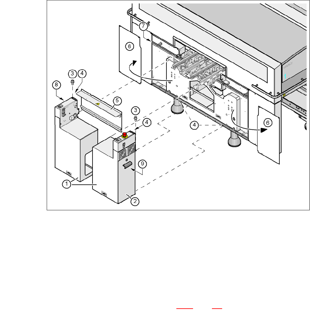
Fig. 4.5 - 15 Install extension kit on the PCB input side
(1) Extension kit, dismantled
(2) Door
(3) Fillister head screw DIN 912, M6x16 and washer
(4) Grounding connection
(5) Transport cover
(6) Side plate, dismantled
(7) Insert rail
(8) Computer unit or Box PC unit (see section 4.5.11
, page 298)
(9) Axis slide in (CA4CA3)
4 Setting Up and Commissioning User Manual SIPLACE CA
4.5 Setting Up the Placement Machine Edition 08/2011 EN
294
Remove both side plates (item 6 in fig. 4.5 - 15).
CAUTION 4
Do not unscrew the three bottom screws straight away. Simply loosen them so that the side
plate does not fall off.
Detach the ground cable from the side plate.
Remove both doors (item 2 in fig. 4.5 - 15) from the extension kit (item 1).
Note: 4
To avoid damage, we recommend that a second person helps to assemble the extension kit.
Place the computer unit/Box PC unit
a
(item 8 in fig. 4.5 - 15) and the axis unit (item 9 in fig.
4.5 - 15
) down at the side of the placement machine, so that you have enough room to fit the
extension kit (item 1 in fig. 4.5 - 15
).
Make sure that the connection cable to the computer unit / Box PC unit and the axis unit is
not under tension.
Lift one half of the extension kit (item 1 in fig. 4.5 - 15) up to the machine frame and position
it so that the mounting bracket lies on the assembly insert rail (item 7 in fig. 4.5 - 15
).
CAUTION 4
Make sure that the extension kit does not collide with the hexagonal shaft of the PCB con-
veyor and thus become bent.
Fasten this half of the extension kit with 2 fillister head screws M6x16 and the corresponding
discs (item 3 in fig. 4.5 - 15
).
Before assembling the second half of the extension kit, fit the conveyor covers (item 5 in fig.
4.5 - 15
). The procedure is as follows:
a)
User Manual SIPLACE CA 4 Setting Up and Commissioning
Edition 08/2011 EN 4.5 Setting Up the Placement Machine
295
4
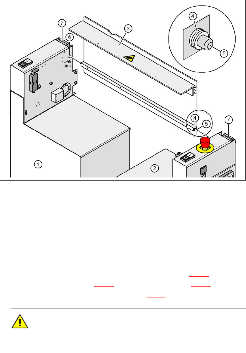
Fig. 4.5 - 16 Fitting the conveyor cover and the second half of the extension kit
(1) Half of the extension kit already fitted
(2) Second half of the extension kit to be fitted
(3) Transport cover
(4) Insert 3 white plastic washers on both sides
(5) Mandrel of the conveyor cover
(6) Hole
(7) Protective cover switch
Insert 3 white plastic discs on each of the two mandrels (item 5 in fig. 4.5 - 16).
Insert the mandrel (item 5 in fig. 4.5 - 16) into the drilling (item 6 in fig. 4.5 - 16).
Lift the second half of the extension kit (item 2 in fig. 4.5 - 16) up to the machine frame.
CAUTION 4
Make sure that this half of the extension kit does not collide with the hexagonal shaft of the
PCB conveyor and thus bend the shaft.