00195941-03-UM SiplaceCA-EN.pdf - 第136页
3 Technical Data User Manual SIPLACE CA 3.4 SIPLACE CA Dimensions and Weight Edition 08/2011 EN 136 3.4.4.4 Machine Feet Clearances and the S tationary Lef t Conveyor Edge for the PCB Single Conveyor 3 Fig. 3.4 - 10 Mach…
User Manual SIPLACE CA 3 Technical Data
Edition 08/2011 EN 3.4 SIPLACE CA Dimensions and Weight
135
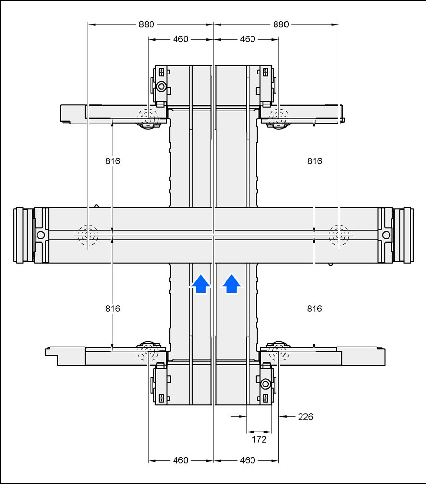
3.4.4.3 Machine Feet Clearances and the Stationary Right Conveyor Edge for the PCB Dual
Conveyor
3
Fig. 3.4 - 9 Machine feet clearances and the stationary right conveyor edge for the PCB dual conveyorin millimeters
3 Technical Data User Manual SIPLACE CA
3.4 SIPLACE CA Dimensions and Weight Edition 08/2011 EN
136
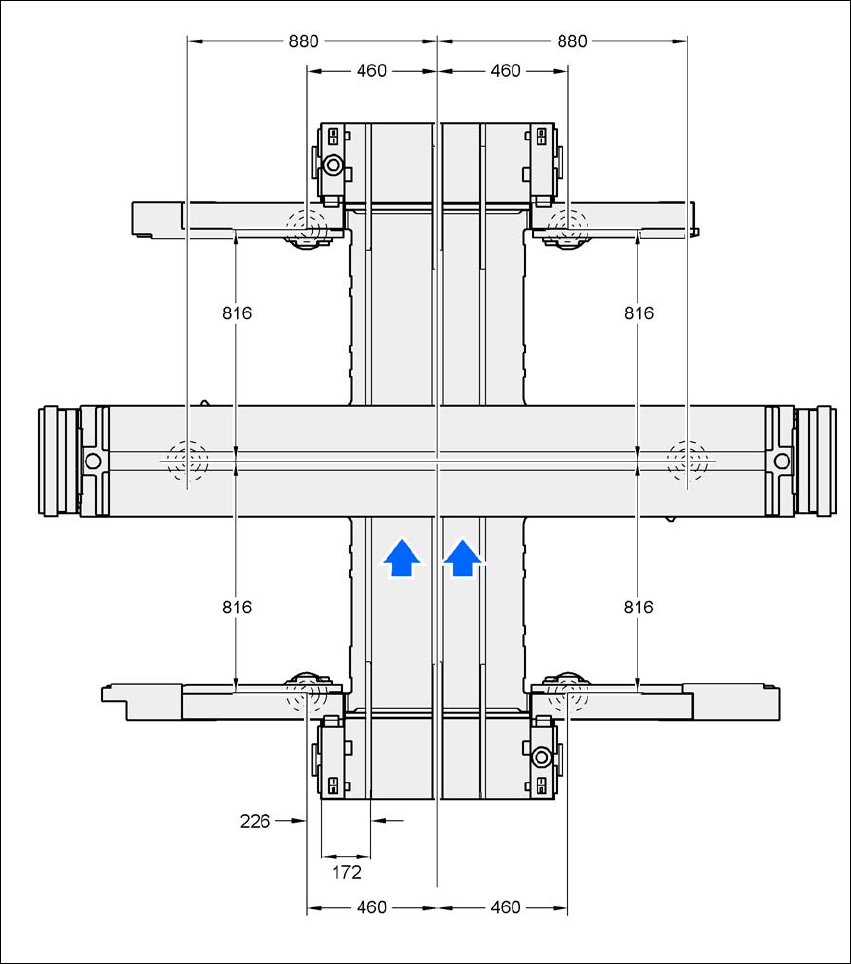
3.4.4.4 Machine Feet Clearances and the Stationary Left Conveyor Edge for the PCB Single
Conveyor
3
Fig. 3.4 - 10 Machine feet clearances and the stationary left conveyor edge for the PCB dual conveyorin millimeters

User Manual SIPLACE CA 3 Technical Data
Edition 08/2011 EN 3.4 SIPLACE CA Dimensions and Weight
137
3.4.5 Technical Data - Dimensions and Weight of Placement Machine
3
Length
With both extension kits 2380 mm
with an extension kit 2103 mm
without extension kits 1826 mm
Width of basic machine
CA4/CA3 incl. monitors, without SWS, without compo-
nent trolley
CA4/CA3 with keyboards, without SWS, without compo-
nent trolley
2766 mm
2804 mm
CA3
Width of whole ma-
chine, -depending on
location assignment
Location 3: Component trolley
Location 4: Component trolley
Location 3: Component trolley
Location 4: SWS
Location 3: SWS
Location 4: Component trolley
Location 3: SWS
Location 4: SWS
Location 1: Component
trolley
Location 2: Component
trolley
--- 3330 mm
a)
3195 mm
a)
3330 mm
a)
Location 1: Component
trolley
Location 2: SWS
3195 mm
a)
3705 mm
a)
3570 mm 3705 mm
a)
Location 1: SWS
Location 2: Component
trolley
3330 mm
a)
3840 mm 3705 mm
a)
3840 mm
Location 1: SWS
Location 2: SWS
3330 mm
a)
3840 mm 3705 mm
a)
3840 mm