00195941-03-UM SiplaceCA-EN.pdf - 第83页
User Manual SIPLACE CA 2 Operational Safety Edition 08/2011 EN 2.8 Safety Equipment 83 2.8.2 Switches and Buttons on the Machine and SWS 2.8.2.1 Position of Switches and Buttons on the Machine and SWS 2 Fig. 2.8 - 3 Posi…
2 Operational Safety User Manual SIPLACE CA
2.8 Safety Equipment Edition 08/2011 EN
82
Function 2
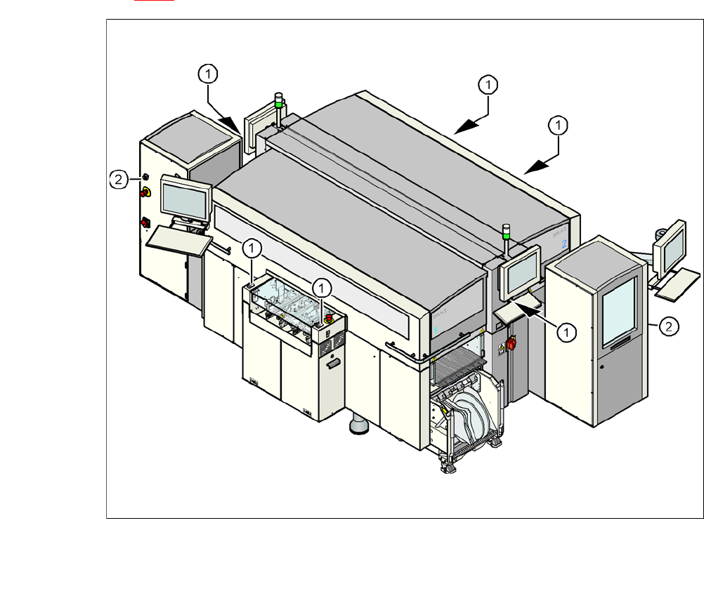
If one of the protective covers is swung upwards or if one of the cover flaps on the PCB conveyor
is lifted, the power supply to the gantry axes and SWS will be immediately interrupted. The gantry
axes and all SWS axes will come to a standstill. The message "Close cover" is displayed on the
screen.
Close the protective covers and press one of the Start buttons on the machine (item 1 in fig.
2.8 - 2
).
2
Fig. 2.8 - 2 Position of start and EMERGENCY STOP reset button (white) on the machine and on the SWS
(1) Start button (white) on the machine
(2) Operating status indicator (white) on the SWS
User Manual SIPLACE CA 2 Operational Safety
Edition 08/2011 EN 2.8 Safety Equipment
83
2.8.2 Switches and Buttons on the Machine and SWS
2.8.2.1 Position of Switches and Buttons on the Machine and SWS
2
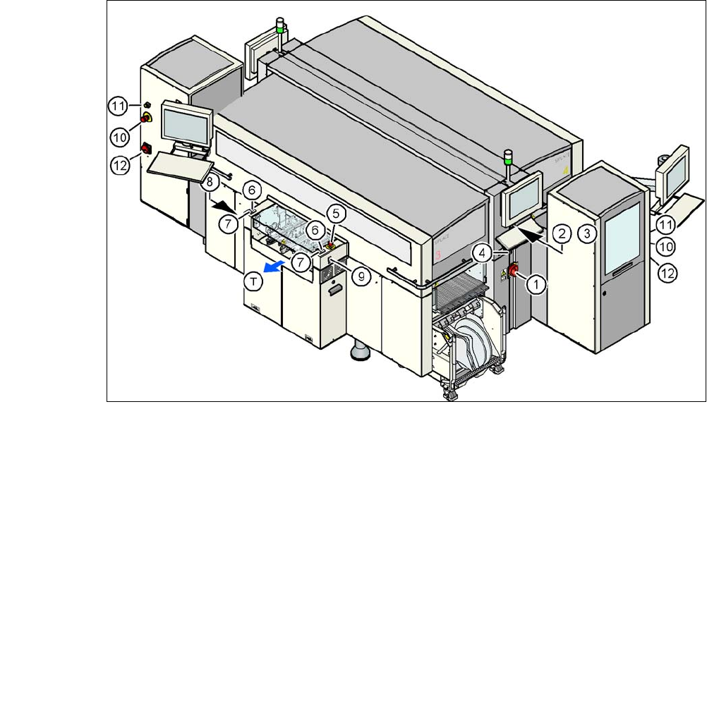
Fig. 2.8 - 3 Position of switches and buttons - View of the PCB output side
(1) Main switch on machine
(2) Stop button (black) on the operator panel on the power supply side
(3) Start button (white) on the operator panel on the power supply side
(4) Component counter on the operator panel on the power supply side
(5) EMERGENCY STOP button on the output side
(6) Start button (white) on the output side
(7) Stop button (black) on the output side
(8) Button (black) for docking the component trolley in or out, location 2
(9) Button (black) for docking the component trolley in or out, location 3
(10)EMERGENCY STOP button on the SWS
(11) Operating status indicator on the SWS
(12)Main switch at the SWS
(T) PCB transport direction
2
2 Operational Safety User Manual SIPLACE CA
2.8 Safety Equipment Edition 08/2011 EN
84
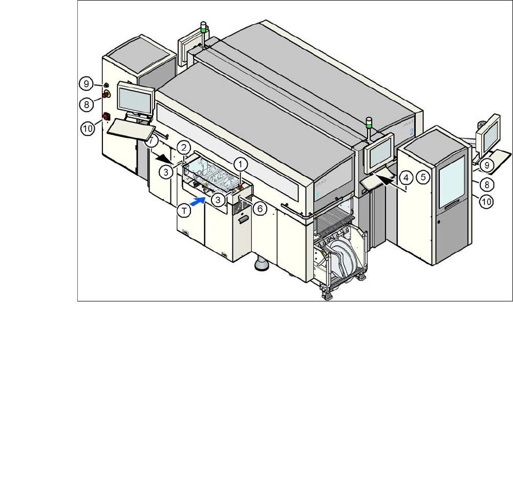
Fig. 2.8 - 4 Position of switches and buttons - View of the PCB input side
(1) EMERGENCY STOP button on the input side
(2) Start button (white) on the input side
(3) Stop button (black) on the input side
(4) Start button (white) on the operator panel on the compressed air unit side
(5) Stop button (black) on the operator panel on the compressed air unit side
(6) Button (black) for docking the component trolley in or out, location 1
(7) Button (black) for docking the component trolley in or out, location 4
(8) EMERGENCY STOP button on the SWS
(9) Operating status indicator on the SWS
(10)Main switch at the SWS
(T) PCB transport direction