00195941-03-UM SiplaceCA-EN.pdf - 第193页
User Manual SIPLACE CA 3 Technical Data Edition 08/2011 EN 3.8 Placement Heads 193 3.8.3.4 T echnical Dat a 3 3.8.3.5 Component Reject Bin Sensor NOTE 3 We recommend to install the opti onal component sensor for the comp…

3 Technical Data User Manual SIPLACE CA
3.8 Placement Heads Edition 08/2011 EN
192
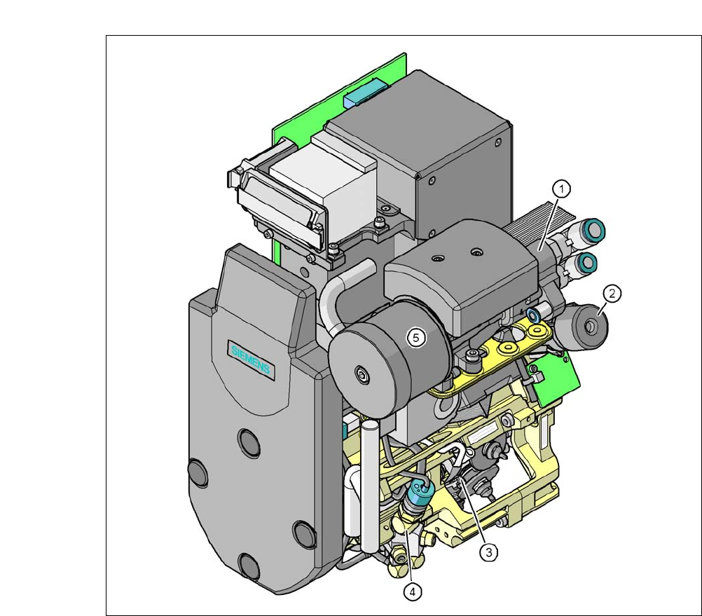
Component Camera (item. 1 in fig. 3.8 - 4) 3
The component camera is fitted to the placement head at star position 11 (item 11 in fig. 3.8 - 5).
It uses a digital interface (hotlink) to exchange data with the vision processor in the axis unit. The
camera is designed to capture the component from underneath. If a component drops onto the
camera, it is removed from the camera field via a removal ramp.
Intermediate Distributor (item 2 in fig. 3.8 - 4) 3
The adapter board is the interface between placement head and placement machine. The vacuum
sensor for the holding circuit is mounted on the star housing.
The following functions are implemented on the adapter board:
– Display the operating voltages at the head
– Display the sensor statuses
– Test access to the CAN bus for the placement head
– Test connector for the signals from the incremental encoder
– Test pins for the analog signals
– Control of the power supply for the incremental encoders for the star and Z drives
– SPI bus interface for the component sensor, the vacuum unit, the "Holding circuit" vac-
uum sensor and the EEPROM
– Signal processing for the output signal from the "Holding circuit" vacuum sensor
– Signal processing for the component sensor signal
– Signal processing for the "Z axis down" sensor
– Signal processing for the CAN bus for the placement head and the machine
– Activation of the return cylinder for the Z axis

User Manual SIPLACE CA 3 Technical Data
Edition 08/2011 EN 3.8 Placement Heads
193
3.8.3.4 Technical Data
3
3.8.3.5 Component Reject Bin Sensor
NOTE 3
We recommend to install the optional component sensor for the component reject bin at a loca-
tion without SWS when a 20 segment Collect&Place head is used. (See section 7.2, page 461)
Range of components
a
a) Please note that the component range that can be placed is also affected by the pad geometry, the customer-spe-
cific standards and the packaging tolerances.
01005 to 2220, Melf, SOT, SOD
Component specifications
Maximum height
Min. lead pitch
Min. lead width
Min. ball pitch
Min. ball diameter
Min. dimensions
Maximum dimensions
Max. weight
4 mm
80 µm
30 µm
100 µm
50 µm
0.12 mm x 0.12 mm
6 mm x 6 mm
1 g
Nozzle types 10xx, 11xx, 12xx
X/Y accuracy (SMD) ± 41 µm/3 , ± 55 µm/4
X/Y accuracy (CA) ± 25 µm/3, ± 33 µm/4
Angular accuracy ± 0.5°/3± 0.7°/4
3 Technical Data User Manual SIPLACE CA
3.8 Placement Heads Edition 08/2011 EN
194
3.8.4 12 Segment Collect & Place CA Head
3
Fig. 3.8 - 6 12 segment Collect&Place CA head - function groups part 1
3
(1) Vacuum generator
(2) Turning station, DP axis
(3) Star with 12 sleeves, star axis
(4) Air kiss valve
(5) Silencer