00195941-03-UM SiplaceCA-EN.pdf - 第275页
User Manual SIPLACE CA 4 Setting Up and Commissioning Edition 08/2011 EN 4.5 Setting Up the Placement Machine 275 Screw the thread of the middle ma chine foot into the hole on the und erside of the spa cer . Align th…
4 Setting Up and Commissioning User Manual SIPLACE CA
4.5 Setting Up the Placement Machine Edition 08/2011 EN
274
Screw the thread of the middle machine foot into the hole on the underside of the spacer.
Align the two spacers on the underside of the machine as follows:
– The opening in the spacer on the pneumatic unit side points in the direction of PCB trans-
port (see item 4 in fig. 4.5 - 3
, page 272).
– The opening in the spacer on the power supply side points in the opposite direction to
that of PCB transport (see item 3 in fig. 4.5 - 3
, page 272).
Fasten both spacers with four hexagon socket-head screws M12x80 each (see item 4 in fig.
4.5 - 4
). Use the size 10 mm screwdriver bit.
Setting the PCB conveyor height to 930 mm and 950 mm 4
You will also need the spacer for PCB conveyor heights of 930 mm and 950 mm.
Align the spacer so that the 122.5 mm side is vertical and the hole for the middle machine foot
points downwards.
4
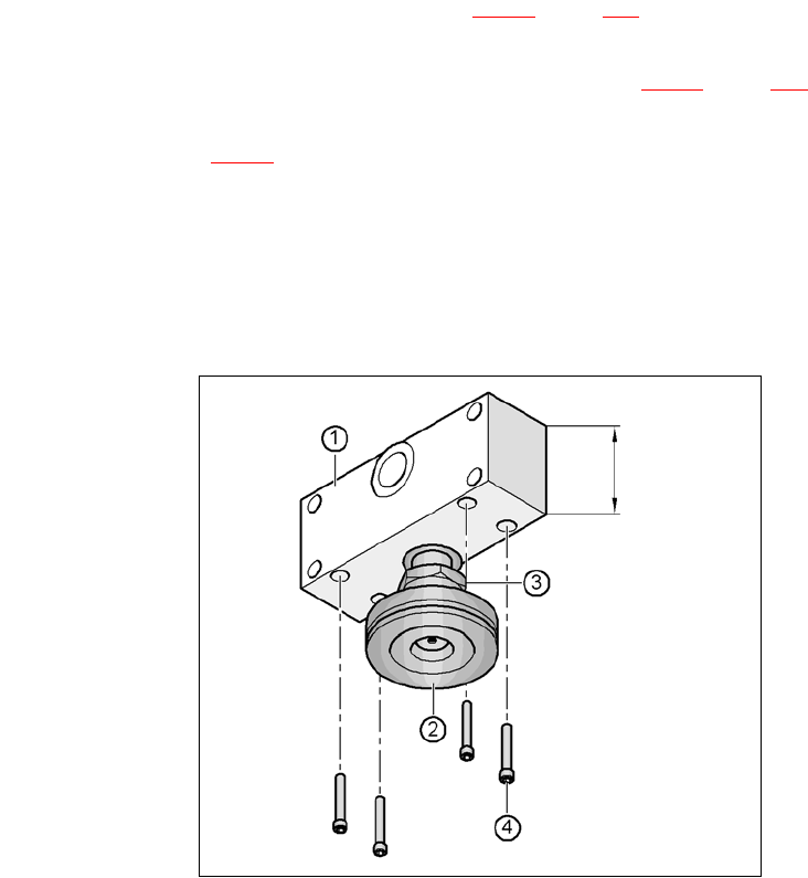
Fig. 4.5 - 5 Alignment of the spacer for conveyor heights of 930 and 950 mm
4
(1) Spacer height 122.5 mm
(2) Machine foot
(3) M24 lock nut
(4) Hexagon socket head screw M12x80, 4x
122,5 mm
User Manual SIPLACE CA 4 Setting Up and Commissioning
Edition 08/2011 EN 4.5 Setting Up the Placement Machine
275
Screw the thread of the middle machine foot into the hole on the underside of the spacer.
Align the two spacers as follows:
– The opening in the spacer on the pneumatic unit side points in the direction of PCB trans-
port (see item 4 in fig. 4.5 - 3
, page 272).
– The opening in the spacer on the power supply side points in the opposite direction to
that of PCB transport (see item 3 in fig. 4.5 - 3
, page 272).
Fasten both spacers with four hexagon socket-head screws M12x80 each (see item 4 in fig.
4.5 - 5
). Use the size 10 mm screwdriver bit.
4.5.4.2 Preadjust the Height of the Outer Machine Feet
4
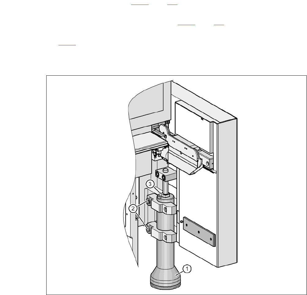
Fig. 4.5 - 6 Preadjust the height of the outer machine feet
(1) Machine foot - 2 versions
(2) M24x90 hexagon socket head screw
(3) M24x2x120 adjusting screw

4 Setting Up and Commissioning User Manual SIPLACE CA
4.5 Setting Up the Placement Machine Edition 08/2011 EN
276
Carefully loosen both hexagon socket-head screws M24x90 (item 2 in fig. 4.5 - 6, page 275)
with the screwdriver bit (wrench size 19 mm) and let the outer machine foot (item 1 in fig. 4.5
- 6, page 275) slowly slide down to the end stop.
Insert the correct machine foot for the required PCB conveyor height.
There are two versions of the outer machine feet: 4
– Outer machine foot for PCB conveyor height 830 mm,
length 369 mm, [03041008-01] (item. 1 in fig. 4.5 - 3
, page 272)
– Outer machine foot for PCB conveyor heights 900, 930 and 950 mm,
length 439 mm, [03000890-02] (item. 2 in fig. 4.5 - 3
, page 272)
Preset the height for each of the outer machine feet.
The distance between the underside of the machine foot and the bottom edge of the machine
frame should be as follows:
Adjust the setting screw M24x2x120 (item 3 in fig. 4.5 - 6, page 275) with the open-ended
wrench SW 36 so that you achieve the distance values from the above table, for the respec-
tive conveyor height.
Carefully lower the placement machine with the fork-lift truck, until the machine feet touch the
floor evenly. A second person should check the stability of the placement machine during low-
ering. If necessary, the clamping of the outer machine feet must be loosened a bit.
Continue to carefully lower the placement machine, until the outer machine feet touch the set-
ting screws M24x2x120 (item 3 in fig. 4.5 - 6
, page 275) for height adjustment.
Make sure that the middle machine feet (see item 2 in fig. 4.5 - 3, page 272) do not touch the
floor. If necessary, screw the middle machine feet further into the placement machine or into
the spacer.
NOTE 4
The description of how to perform final placement machine adjustment can be found in sec-
tion 4.5.17, page 316.
PCB transport height Distance from underside of machine foot
to bottom edge of machine frame
830 mm 120 mm
900 mm 190 mm
930 mm 220 mm
950 mm 240 mm