00195941-03-UM SiplaceCA-EN.pdf - 第63页
User Manual SIPLACE CA 2 Operational Safety Edition 08/2011 EN 2 .3 Warning Labels on the SWS 63 2.3.5 W arning Label W209 on th e EMERGENCY STOP Button 2 Fig. 2.3 - 9 W209 [03009349-01] (number per SWS: 1) 2 2 Fig. 2.3 …
2 Operational Safety User Manual SIPLACE CA
2.3 Warning Labels on the SWS Edition 08/2011 EN
62
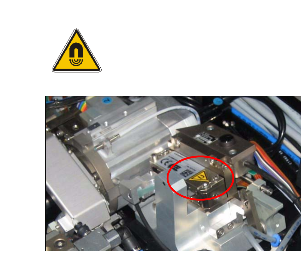
2.3.4 Warning Label on the Flip Unit and the Die Attach Unit
2
Fig. 2.3 - 7 W13 (number on the die attach unit: 1, number on the flip unit: 1)
Fig. 2.3 - 8 Warning label on the die attach unit
2
2
2
Magnetic field warning
User Manual SIPLACE CA 2 Operational Safety
Edition 08/2011 EN 2.3 Warning Labels on the SWS
63
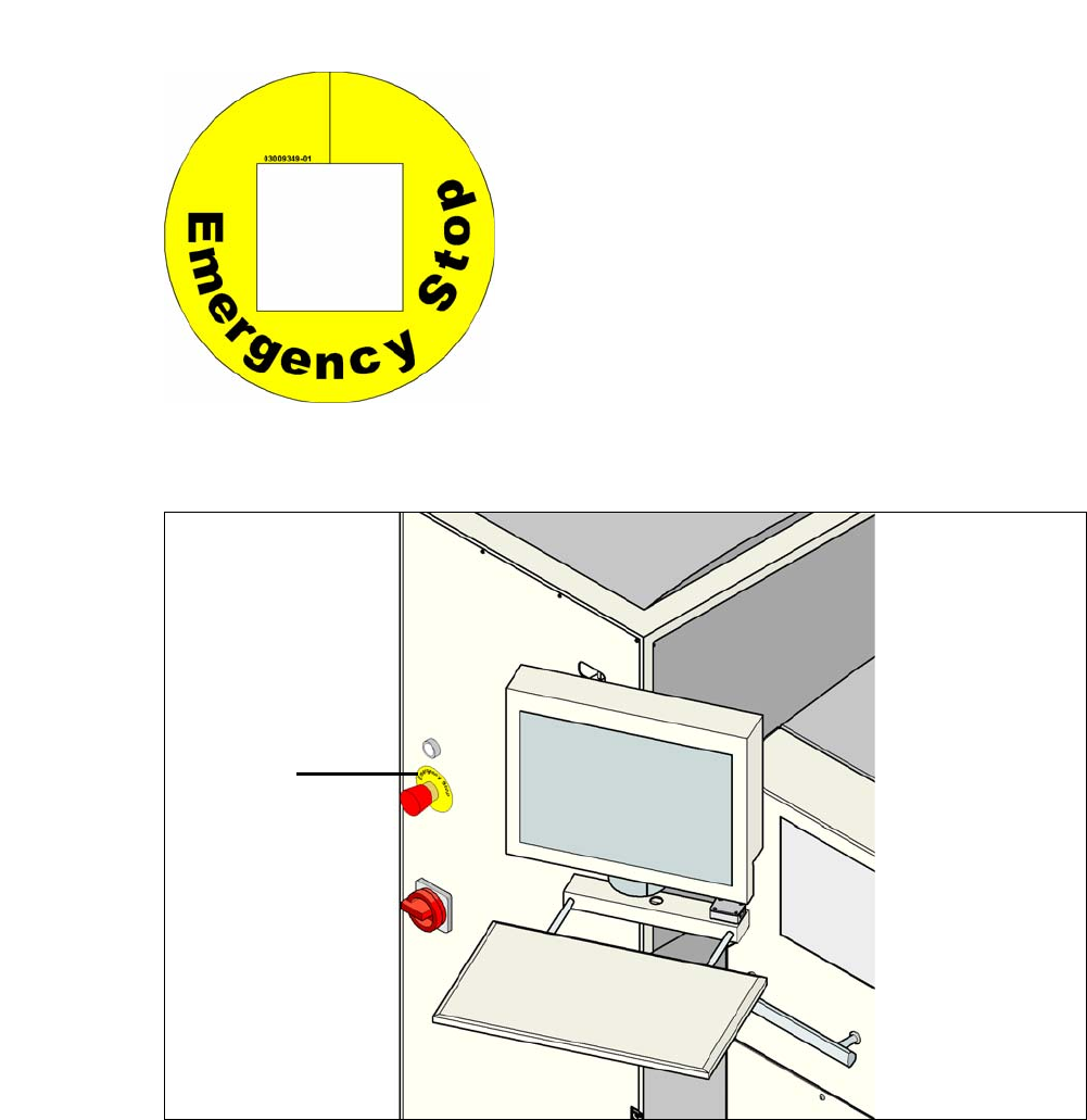
2.3.5 Warning Label W209 on the EMERGENCY STOP Button
2
Fig. 2.3 - 9 W209 [03009349-01] (number per SWS: 1)
2
2
Fig. 2.3 - 10 Warning Label W209 on the EMERGENCY STOP Button
2
2
2
2
2
2
2
2
2
2
2
2
2
2
2
2
2
2
2
For Australia, Canada, Mexico and USA, warn-
ing label W209 is affixed to the extension kit in-
stead of the yellow ring on the EMERGENCY
STOP buttons.
W209

2 Operational Safety User Manual SIPLACE CA
2.4 Laser Classification Edition 08/2011 EN
64
2.4 Laser Classification
2.4.1 Laser Class 1
2.4.1.1 Classification of Whole Machine
2
Note: 2
Modules in laser classes 1 and 1M are not identified.
2.4.1.2 Classification of Camera Systems
2
2
All installed camera systems and the whole machine when ready for oper-
ation are assigned to laser class 1.
The laser classes are determined according to DIN EN 60825-1:2001.
2
The following camera systems are assigned to laser class 1:
– PCB camera multicolor, Type 24, digital
– Component cameras for the SIPLACE TwinHead
Stationary P&P component camera, type 33, 55 x 45, digital
Stationary P&P component camera, type 25, 16 x 16, digital