00195941-03-UM SiplaceCA-EN.pdf - 第467页
User Manual SIPLACE CA 7 Station Enlargements Edition 08/2011 EN 7.6 PCB Barcode Scanner 467 7.6 PCB Barcode Scanner 7.6.1 Overview [ 7 The PCB barcode scanner is us ed to automatically record and deco de barcodes on PCB…

7 Station Enlargements User Manual SIPLACE CA
7.5 PCB Camera Multicolor, Type 24, Digital Edition 08/2011 EN
466
7.5.3 Illumination Types
The following types of illumination can be selected on the multicolor PCB camera:
– White illumination
This type of illumination is used for standard PCBs with tinned fiducials.
– Blue oblique illumination
In most cases, this can be used to greatly improve the contrast with bright fiducials on a light
base material, such as ceramic or CEM. Fiducials covered with solder resist can also be de-
tected better on a light background.
– Infrared illumination
This type of illumination is particularly useful for fiducials that are covered with solder resist
or for fiducials on flex materials. When using silver or platinum fiducials on a ceramic base,
this type of illumination could also achieve better recognition results. This should be checked
in advance by performing a test centering/placement run.
7.5.4 Fiducials and Inkspot Criteria
Fiducial and inkspot criteria are described in section 3.13.6.3 and 3.13.6.4, page 232.
User Manual SIPLACE CA 7 Station Enlargements
Edition 08/2011 EN 7.6 PCB Barcode Scanner
467
7.6 PCB Barcode Scanner
7.6.1 Overview
[ 7
The PCB barcode scanner is used to automatically record and decode barcodes on PCBs. The
PCB barcode scanner sends the read data via its serial interface to the transport controller and
then for further processing to the machine controller via the CAN bus.
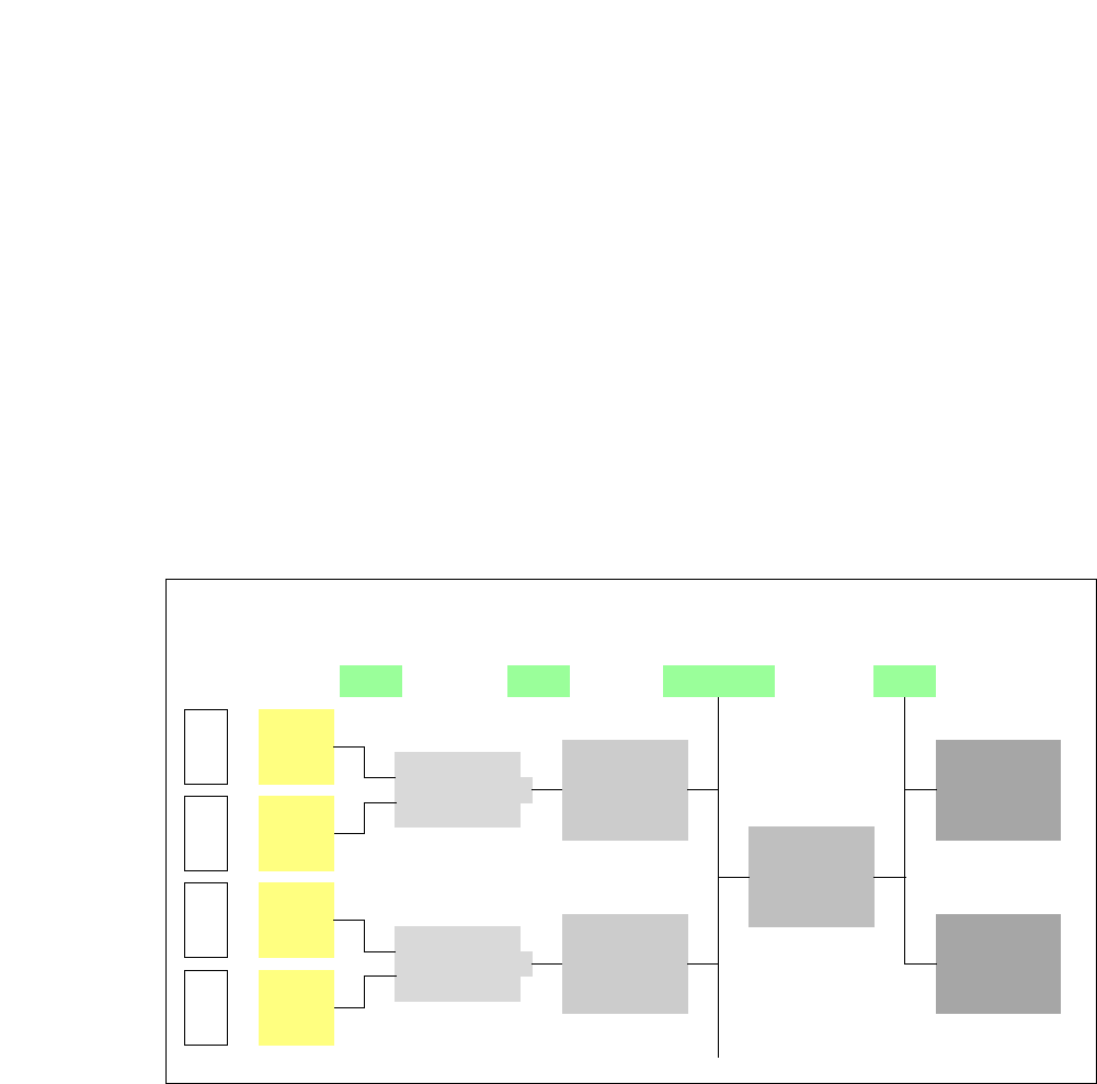
Fig. 7.6 - 1 PCB barcode block diagram
7
[00176117-XX] Cognex DataMan 100X
[00176112-XX] Assembly kit for DataMan X/HS/HF series topside
(for reading barcodes on the topside of the PCB, one per
barcode scanner)
[00176113-XX] Assembly kit for DataMan X/HS/HF series underside
(for reading barcodes on the underside of the PCB, one
per barcode scanner)
[00176118-XX] Cognex I/A module (one per SIPLACE line)
[00176119-XX] Cognex USB cable DM 100 USB (one per SIPLACE line)
[00176120-XX] Wiring for interface I/A box (one per SIPLACE line)
Device number
1
Barcode
scanner
topside
Distribution
board
Transport
controller,
right
Barcode
scanner
under-
2
3
Barcode
scanner
topside
Distribution
board
Transport
controller,
left
Barcode
scanner
under-
4
Machine
controller
Station
computer
SIPLACE Pro
computer
LANCAN busV-24V-24
7 Station Enlargements User Manual SIPLACE CA
7.6 PCB Barcode Scanner Edition 08/2011 EN
468
The PCB barcode scanners are installed on the input side of the placement machine on the PCB
conveyor. Up to four devices can be retrofitted to each machine. The barcode scanners are fitted
so that the barcode labels on the topside and underside of the PCBs can be scanned on both
tracks of the dual conveyor.
The barcode scanners are available for 1D and 2D codes.
The PCB barcode scanners are fixed to the top and bottom profiled rail using retainers. These can
be positioned as required on the profiled rails, and aligned with respect to the barcode labels. De-
pending on the position of the barcodes, the barcode scanner can be easily assembled so that it
can read the barcodes lengthwise or at right angles to the direction of board transport.
7.6.2 Functional Description
The PCB barcode scanner supports the flexible manufacture of SMD products, and increases
placement reliability. It recognizes all the code types conventionally used in industrial applications.
The PCB barcode scanner reads the barcode label on the topside or underside of each incoming
PCB as they are transported onto the input conveyor. Based on the barcode information, the
SIPLACE Pro computer automatically selects the correct placement program from the previously
created barcode allocation list and sends this to the station. If a barcode filter is defined, only in-
formation that is identified as relevant within the barcode is compared. This procedure is carried
out time neutrally during placement of the PCB already in the machine. If several PCBs with the
same barcode enter in succession, the program is only transferred the first time. The following re-
quirements apply to all products to be produced using the PCB barcode:
– The component setup must be identical on all the machines on the line
– All PCBs must be of the same width