00195941-03-UM SiplaceCA-EN.pdf - 第20页
1 Introduction User Manual SIPLACE CA 1.1 Machine D escription Edition 08/2011 EN 20 1.1 Machine Description The SIPLACE CA placement systems are known fo r high configuration flexibility , placement per- formance and pr…
User Manual SIPLACE CA 1 Introduction
Edition 08/2011 EN
19
1 Introduction
This operating manual is designed as a source of information and reference for those persons op-
erating and setting up the CA series placement machines.
1
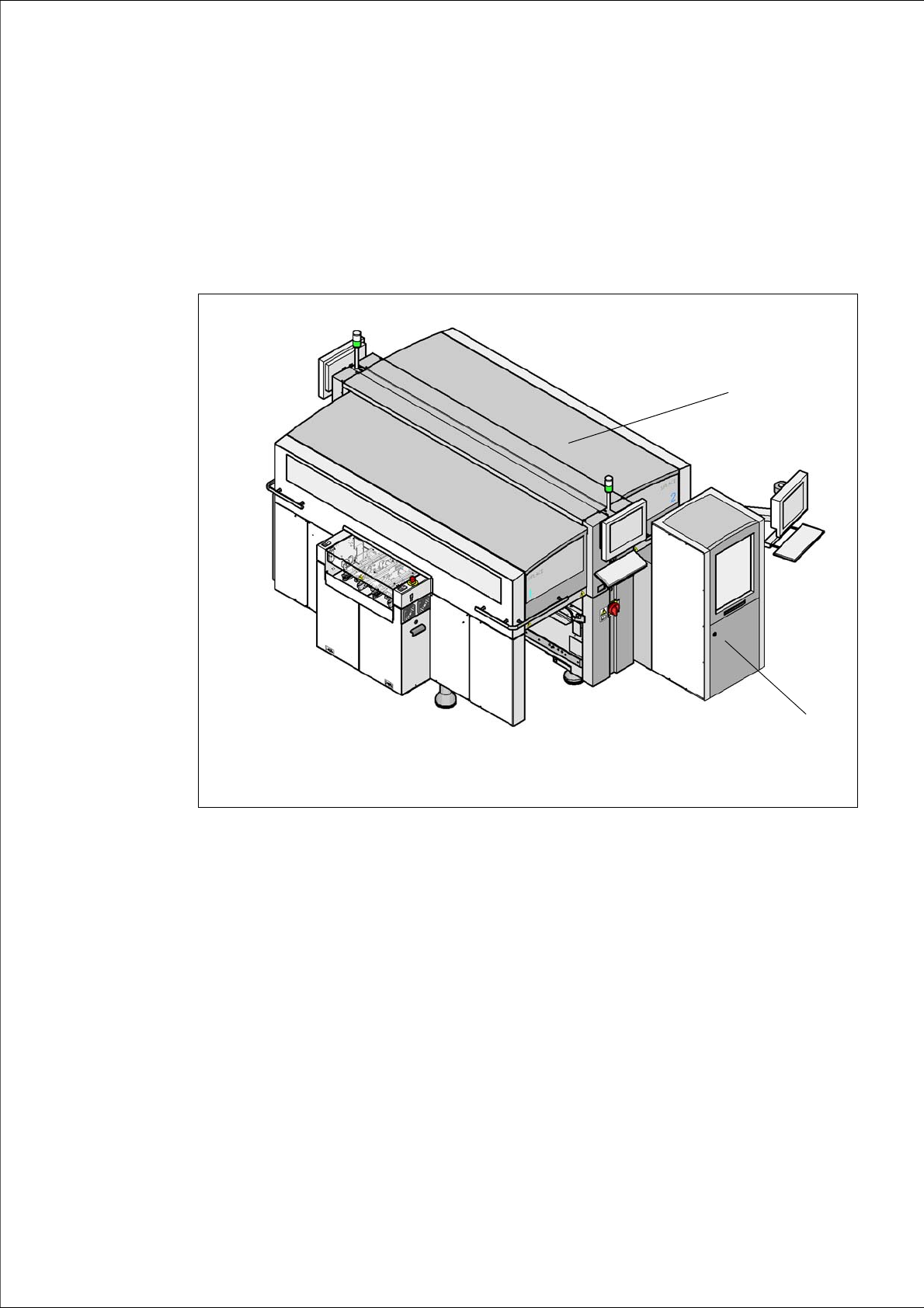
Fig. 1.0 - 1 SIPLACE CA4 placement machine with SIPLACE Wafer System (SWS)
(1) SIPLACE CA4
(2) SIPLACE Wafer System (SWS)
The header of each chapter contains the
– release and
– software version
valid from this issue. 1
1
2

1 Introduction User Manual SIPLACE CA
1.1 Machine Description Edition 08/2011 EN
20
1.1 Machine Description
The SIPLACE CA placement systems are known for high configuration flexibility, placement per-
formance and precision. The placement machines of the SIPLACE CA series are available in two
variants:
– SIPLACE CA3, the placement machine with 3 gantries and
– SIPLACE CA4, the placement machine with 4 gantries.
The SIPLACE CA can place bare dies directly from the wafer, by using the flip chip or die attach
process, and can also place the entire SMD spectrum covered by the SIPLACE X machines. Two
placement variants are being used at the placement machine:
– the Collect&Place-method for highspeed placement of standard components
– the Pick&Place-method for highspeed placement of special components in the Fine Pitch
and Super Fine Pitch area
The SIPLACE is based on the well-proven hardware and software of the SIPLACE X machine.
Several changes in the hard and software permit operations on the SIPLACE CA running the
brand new designed SIPLACE Wafer System (SWS) with the same user interface for the SI-
PLACE Pro and station software. The placement machine is equipped with at least one SWS in
one of the four locations, to be able to place dies from the wafer. The Siplace CA can be operated
without a SWS and thus can be used like a X machine. This makes the components (dies) directly
available to the placement head, in so-called wafers. The SWS is available in the following variant:
– SWS 12 for wafers on wafer frames up to 15“
The gantries that are driven by linear motors can be positioned fast and precisely in X and Y di-
rection. There is a placement head on each gantry.
The moving head picks the components up from the waiting SWS and places them on the waiting
printed circuit board. This proven SIPLACE principle has many advantages:
– No downtime due to refilling or splicing
– safe pick up of even the smallest components
– no shifting of the components on the circuit board
– minimised travel range
High flexibility, economic efficiency and reliable setups are the guarantee for the high level of pro-
ductivity in the SIPLACE CA placement systems. Minimum down times increase utilization and
thus help to increase productivity. Even small 01005 components can be processed with the SI-
PLACE CA series.

User Manual SIPLACE CA 1 Introduction
Edition 08/2011 EN 1.1 Machine Description
21
1.1.1 The SIPLACE Principle
The SIPLACE Wafer Systems make bare dies available in fixed pickup positions, for pickup with
the die attach or flip chip methods. The other components are made available by the fixed feeders
on the component trolley and on the trays of the Matrix Tray Changer. The placement heads pick
the bare dies and components up and place these on the waiting printed circuit boards.
The placement machines in the CA series have two placement areas:
– As in the case of SIPLACE X machines, up to two boards can be processed simultaneously
for single conveyors and up to four boards can be processed at the same time for dual con-
veyors.
The principle of the "stationary component supply" and "stationary PCB", which has proved highly
suitable for all SIPLACE placement machines, has a number of significant advantages:
– The refilling of components or splicing on of new tapes does not cause machine standstill.
– The vibration-free feeding in of components enables reliable pickup of even the smallest com-
ponents (e.g. 01005) and bare dies.
– The PCB, which does not move during the placement process, prevents the components slip-
ping.
– The combination of placement heads with nozzle changers always guarantees an optimum
nozzle configuration for every placement process, thus minimizing traversing paths and opti-
mizing the placement sequence.
High flexibility, economic efficiency and reliable setups are the guarantee for the high level of pro-
ductivity in the SIPLACE CA series. Minimum down times increase utilization and thus help to in-
crease productivity.
Since this new concept combines at least two production lines to form a single line (SMD and bare
die placement), the investment costs and cost of ownership can be reduced significantly.