00195941-03-UM SiplaceCA-EN.pdf - 第325页
User Manual SIPLACE CA 4 Setting Up and Commissioning Edition 08/2011 EN 4.6 Installing the SWS 325 4.6.3.4 Final Adjustment of the SWS Use the fork-lift truck or han d lift to push the SWS carefully into the pla cemen…
4 Setting Up and Commissioning User Manual SIPLACE CA
4.6 Installing the SWS Edition 08/2011 EN
324
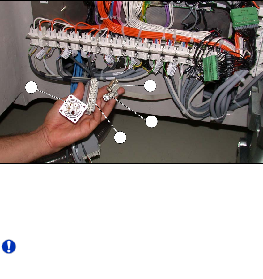
Fig. 4.6 - 3 Position of the connections on the placement machine
(1) CAN Bus connection X1x5
(2) CAN Bus connection X1x6
(3) Compressed air connection (modified dummy connector [03011592-01])
(4) FFI communication connection X1x3
Note: 4
Connect the SWS to the placement machine before performing alignment and final adjustment,
as the connection points will no longer be accessible after installation.
1
2
3
4
User Manual SIPLACE CA 4 Setting Up and Commissioning
Edition 08/2011 EN 4.6 Installing the SWS
325
4.6.3.4 Final Adjustment of the SWS
Use the fork-lift truck or hand lift to push the SWS carefully into the placement machine, as
far as the stop on the bumper.
Carefully lower the SWS with the fork-lift truck or hand lift, until it lies evenly on the contact
bars of the placement machine.
CAUTION 4
Make sure that you do not lower the hand lift too far, before fastening the screws, as the SWS
will then tip over towards the magazine lift. 4
A second person should check the stability of the SWS during lowering. 4
The following screws are needed to install the SWS:
–3x M8
–2x M6
– 4x M6 for the angle bracket (2 at the location, 2 at the wafer table)
– 1x fitting screw
Note: 4
During final installation, observe the following order of screws.
Fasten the rear clamping claw (6) loosely, with one M8 screw.
Insert the remaining screws and tighten loosely.
NOTE 4
The correct position of the SWS is ensured with the help of the fitting screw and the contact
rods in the placement machine. 4
Fasten the M6 screws (item 4 and 5) in succession, with a torque of 10 Nm.
Fasten the M8 screws (item 1, 2 and 6) in succession, with a torque of 18 Nm.
Tighten the fitting screw in item 3 with a torque of 13-14 Nm.
Tighten the angle bracket for fixing the wafer table with the M6 screws (items 7 and 8).
Fix the angle bracket with the M6 screws to the wafer table.
4 Setting Up and Commissioning User Manual SIPLACE CA
4.6 Installing the SWS Edition 08/2011 EN
326
4
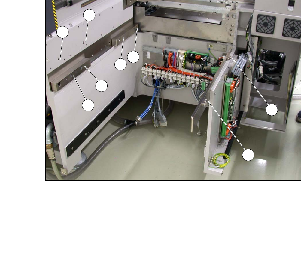
Fig. 4.6 - 4 Picture showing the position of screws for the SWS at the SIPLACE location
You can now remove the fork-lift truck or hand-lift.
(1) M8 (2) M8
(3)Fitting screw (4)M6
(5) M6 (6) M8 for clamping claw
(7) M6 for angle bracket (8) M6 for angle bracket
2
3
5
4
1
7
8
6