00195941-03-UM SiplaceCA-EN.pdf - 第401页
User Manual SIPLACE CA 6 Component and Die Handling Edition 08/2011 EN 6.2 Component Trolley, SIPLACE X-Series 401 6.2 Component T rolley , SIPLACE X-Series [001 19722-xx] Component trolley for SIPLACE X series Up to thr…
6 Component and Die Handling User Manual SIPLACE CA
6.1 X Feeder Modules for the Component Trolley from the SIPLACE X Series Edition 08/2011 EN
400
6
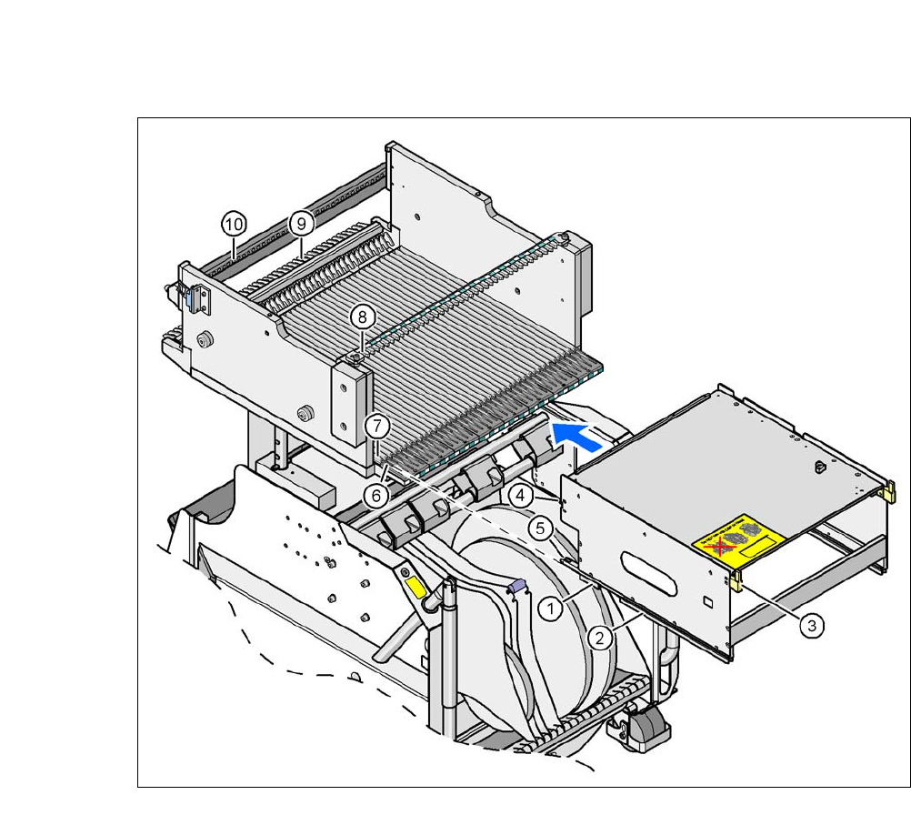
Fig. 6.1 - 18 Inserting a waffle-pack tray holder for the component trolley from the SIPLACE X-series
(1) Front slider guide (6) Insertion aid
(2) Back slider guide (7) Slide bar (omega profile)
(3) The back centering pin (8) Recess in the centering bar for holding the
"back" centering pin
(4) Front centering pin (9) Locking latches
(5) Locking roller (10)Centering holes at the component table for re-
ceiving the front centering pin
User Manual SIPLACE CA 6 Component and Die Handling
Edition 08/2011 EN 6.2 Component Trolley, SIPLACE X-Series
401
6.2 Component Trolley, SIPLACE X-Series
[00119722-xx] Component trolley for SIPLACE X series
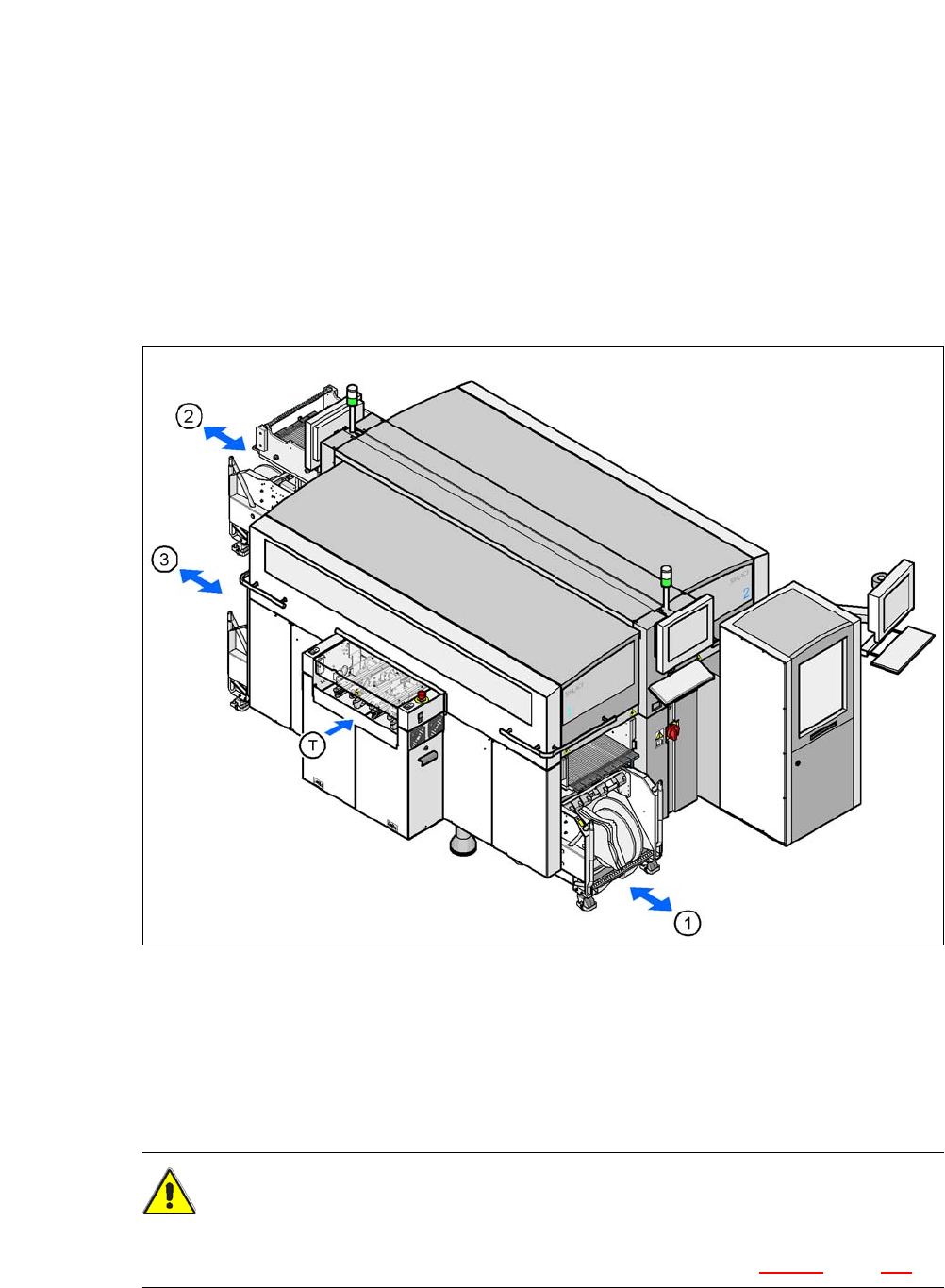
Up to three SIPLACE X series component trolleys can be docked onto the SIPLACE CA series
machines. The locations are numbered. The following diagram shows the CA4 with an SWS at
location 2 as an example.
6
Fig. 6.2 - 1 Component trolley locations, SIPLACE X-series - example showing an SWS at location 2
(1) Location 1
(2) Location 3
(3) Location 4
(T) PCB direction of travel
CAUTION 6
The component trolleys of the SIPLACE X series may only be docked onto locations which are
equipped with the SIPLACE X series component trolley docking units (fig. 5.12 - 3, page 370).
6 Component and Die Handling User Manual SIPLACE CA
6.2 Component Trolley, SIPLACE X-Series Edition 08/2011 EN
402
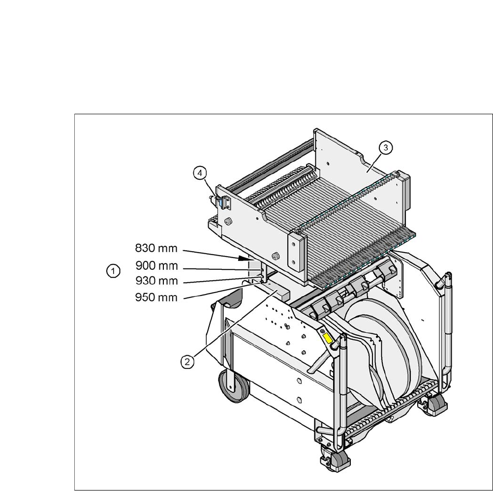
The component trolleys are independent modules, which can be set up with feeder modules at an
external set up location. This means that the production process only has to be interrupted briefly
in order to change the component trolley.
6
Fig. 6.2 - 2 Component trolley, SIPLACE X-series with a PCB conveyor height of 950 mm
6
(1) Holes for the PCB conveyor heights 900, 930 and 950 mm in the guide columns. For the
830 mm conveyor height, the component table lies on the block (2).
(2) Supporting block
(3) Component table
(4) Reed switch for switching the safety switch in the component trolley docking unit