00195941-03-UM SiplaceCA-EN.pdf - 第88页
2 Operational Safety User Manual SIPLACE CA 2.8 Safety Equipment Edition 08/2011 EN 88 Main switch in OFF position 2 W ARNING Individual SWS components can still carry potentially lethal volt ages even if the main power …

User Manual SIPLACE CA 2 Operational Safety
Edition 08/2011 EN 2.8 Safety Equipment
87
Protective cover switches 1, 2, 3 and 4 (item 1, 2, 3 and 4 in fig. 2.8 - 5) and protective switch
for the cover flaps on the input and outputs of the PCB conveyor (item 5 and 6 in fig.
2.8 - 5)2
These switches check whether the protective covers and the cover flaps are closed. When they
are closed, the EMERGENCY STOP contact and the signaling contact are closed. If one of the
covers or the cover flaps is opened, the EMERGENCY STOP contact and the signaling contact
open. Individual components will be disabled or will remain enabled (see fig. 2.8 - 8
, page 94).
NOTE
If the protective cover of the SIPLACE machine is opened, the SWS is also in EMERGENCY
STOP state. 2
2.8.2.3 Function of Switches and Buttons on the SWS
EMERGENCY STOP button, latching, with override protection according to EN 418 2
The EMERGENCY STOP button is red and latches in the ON position when pressed. If the EMER-
GENCY STOP button is pressed, the switching contact opens the EMERGENCY STOP circuit.
Both SIPLACE and SWS EMERGENCY STOP circuit are interrupted. The corresponding EMER-
GENCY STOP switching devices switch the contactors off (delayed by 500 ms).
The operating status indicator (white) is switched off.
The EMERGENCY STOP message is displayed. The SIPLACE detects the location where the
EMERGENCY STOP button was pressed.
To reset the EMERGENCY STOP at the SWS, the EMERGENCY STOP button on the SWS must
be released. The EMERGENCY STOP circuit of the SIPLACE must be closed (protective covers
closed) and one of the start buttons on the SIPLACE must be pressed.

2 Operational Safety User Manual SIPLACE CA
2.8 Safety Equipment Edition 08/2011 EN
88
Main switch in OFF position 2
WARNING
Individual SWS components can still carry potentially lethal voltages even if the main power switch
is switched off:
Death, serious injury or considerable damage may result if these automatic placement sys-
tems are handled incorrectly.
Always follow the applicable accident prevention and DIN regulations (particularly DIN EN 60
204, part 1) and the applicable regulations in your own country.
The safety door to the power supply must ONLY be opened by appropriately qualified and
trained personnel.
Main switch in ON position 2
The SWS computer starts when the main switch is switched on.
User Manual SIPLACE CA 2 Operational Safety
Edition 08/2011 EN 2.8 Safety Equipment
89
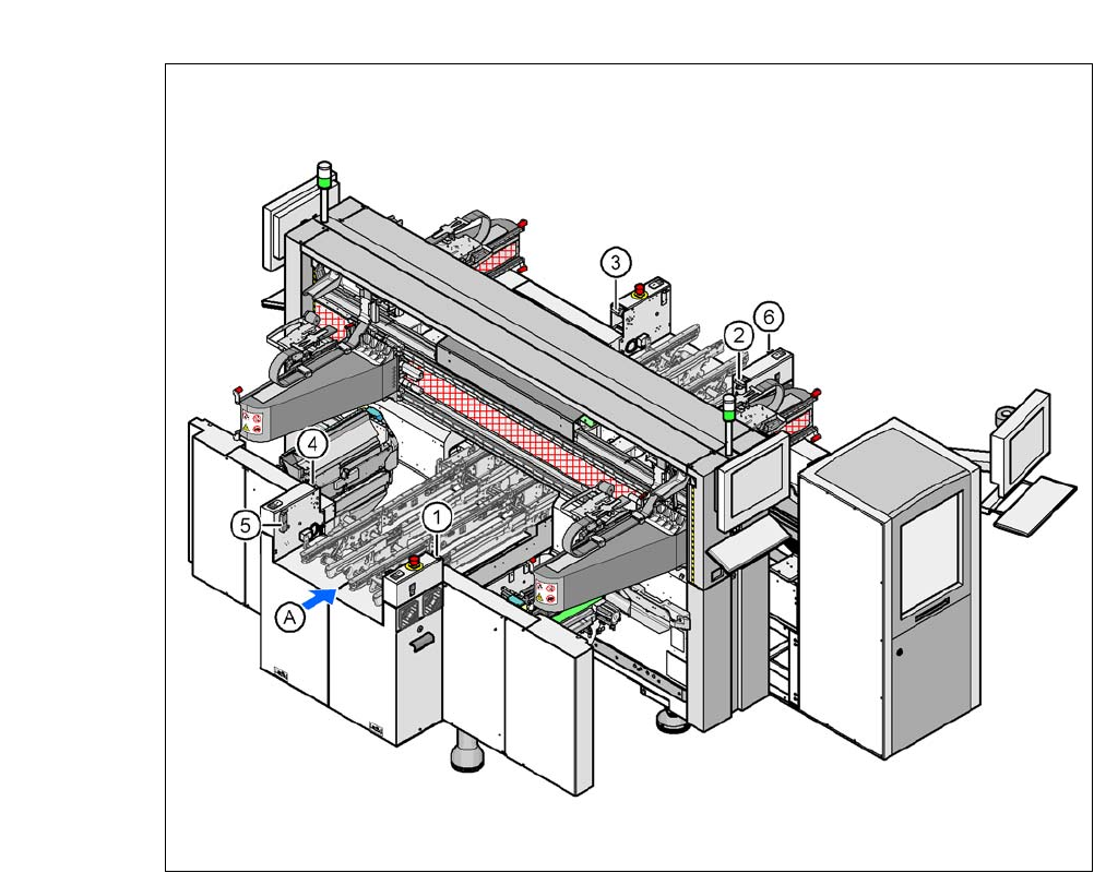
2.8.2.4 Position of Protective Switches at the Machine
2
Fig. 2.8 - 5 Position of protective switches at the machine
2
(1) Protective cover switch, location 1
(2) Protective cover switch, location 2
(3) Protective cover switch, location 3
(4) Protective cover switch, location 4
(5) Protective switch for the cover flap on the PCB conveyor input side
(6) Protective switch for the cover flap on the PCB conveyor output side
(A) PCB transport direction