00195941-03-UM SiplaceCA-EN.pdf - 第368页
5 Tasks on the Mach ine User Manual SIPLACE CA 5.12 Docking the Component Trolley In or Out Edition 08/2011 EN 368 5.12 Docking the Componen t T rolley In or Out 5.12.1 Safety Instructions for Docki ng Component T rolley…

User Manual SIPLACE CA 5 Tasks on the Machine
Edition 08/2011 EN 5.10 Refilling Components at the Changeover Table
367
5.10 Refilling Components at the Changeover Table
The online help contains information on refilling components with and without barcodes.
When using tape feeders, make sure that you always splice on a new tape in good time, so
that the feeders do not run empty.
However, do not splice the tapes too early because if you wind the tape onto the new reel
after splicing the end of the old tape, the reel with the new tape may be overfilled. The tape
could then slip off the reel and become tangled. Under certain circumstances, this could
cause pickup errors and prolonged down times.
When using tape reels of 15" (381 mm) and higher, always use spindles (see fig. 5.4 - 4) and
make sure that the partition plates are inserted correctly (see fig. 5.4 - 3
).
5.11 Refilling Components at the SWS with Wafer
Changer System
When all wafers of one die type have been processed, (note on the user interface ) remove
the magazine from the magazine lift and replace the processed wafer.
Alternatively an entire processed wafer magazine can also be replaced by a further, already
prepared magazine with new wafers.
5 Tasks on the Machine User Manual SIPLACE CA
5.12 Docking the Component Trolley In or Out Edition 08/2011 EN
368
5.12 Docking the Component Trolley In or Out
5.12.1 Safety Instructions for Docking Component Trolleys In and Out
WARNING 5
To prevent accidents (risk of crushing), the component trolley may only be docked in or out by
one person.
5
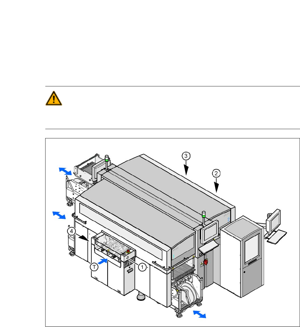
Fig. 5.12 - 1 Safety instructions for docking the component trolley in or out
(1) Button for docking the component trolley in or out, location 1
(2) Button for docking and undocking the component trolley, location 2 (without function here, as
the location is occupied with an SWS)
(3) Button for docking the component trolley in or out, location 3
(4) Button for docking the component trolley in or out, location 4
(T) Direction of PCB transport
User Manual SIPLACE CA 5 Tasks on the Machine
Edition 08/2011 EN 5.12 Docking the Component Trolley In or Out
369
The safety concept for the component trolley changeover prescribes that the user presses a but-
ton (item 1, 2, 3 or 4 in fig. 5.12 - 1
) on the input or output side of the machine, to dock or undock
the component trolley. This ensures that the operator is always standing to the side of the place-
ment machine. In addition, the component trolley can only be docked in if the protective covers
are closed.
5.12.2 Docking Out the Component Trolley
Click on the STOP PROCESSING PCB icon in the MAIN VIEW menu.
The PCB in progress will be completed. The icons of the SINGLE FUNCTIONS menu will
then be activated. 5
Click on the desired icon SINGLE FUNCTIONS GANTRY.
Select GANTRY FUNCTIONS.
From this menu, click on the GO TO SET-UP POSITION button.
All the placement heads will move across the PCB conveyor to prevent them being dam-
aged when the component trolley is changed. 5
Press the appropriate button on the input or output side of the machine (item 1, 2, 3 or 4 in
fig. 5.12 - 1
) until the component trolley is undocked.
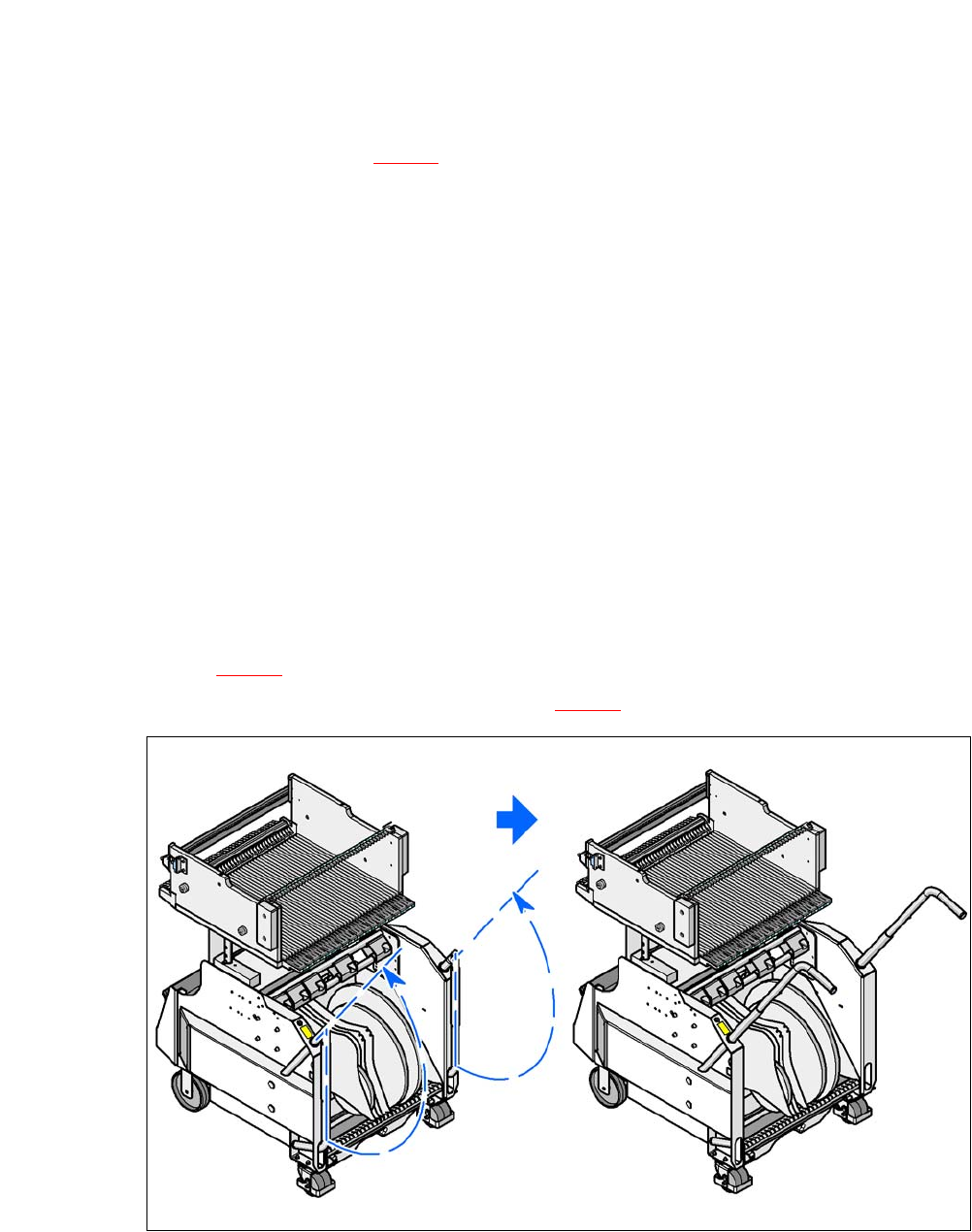
Swing both handles upwards (item 1 in fig. 5.12 - 2).
5
Fig. 5.12 - 2 Component trolley - swivel handles up to push
5
With both hands on the handles, pull the component trolley out of the placement machine.