00195941-03-UM SiplaceCA-EN.pdf - 第280页
4 Setting Up and Commissioning User Manual SIPLACE CA 4.5 Setting Up the Placement Machine Edition 08/2011 EN 280 4.5.7.2 Setting Up 4 Fig. 4.5 - 8 Install extension kit to the PCB output side (1) Extension kit (2) Door …

User Manual SIPLACE CA 4 Setting Up and Commissioning
Edition 08/2011 EN 4.5 Setting Up the Placement Machine
279
Dismantle the cable covers (item 3 and 5 in fig. 4.5 - 7) from the sides (item 1 in fig. 4.5 - 7)
of the output conveyor.
Place the side (item 1 in fig. 4.5 - 7) carefully on the side of the processing conveyor (item 2
in fig. 4.5 - 7
).
CAUTION 4
Be careful not to cut through any of the light barrier or drive motor cables.
Fasten each side with 4 fillister head screws M6x16 and the corresponding discs (item 7 in
fig. 4.5 - 7
).
Connect the power cable to the light barriers and drive motors.
Fasten the cable covers (item 3 and 5 in fig. 4.5 - 7).
Insert the hexagonal shaft (item 9 in fig. 4.5 - 7) into the drive unit (item 10 in fig. 4.5 - 7).
Make sure that the hexagonal shaft guidance (item 8 in fig. 4.5 - 7) is always pointing towards
the conveyor side on which the drive unit (item 10 in fig. 4.5 - 7
) is fixed.
4.5.7 Install Extension Kit to the PCB Output Side
4.5.7.1 Tools
– Allen keys, DIN 911, set
– Machine key
4 Setting Up and Commissioning User Manual SIPLACE CA
4.5 Setting Up the Placement Machine Edition 08/2011 EN
280
4.5.7.2 Setting Up
4
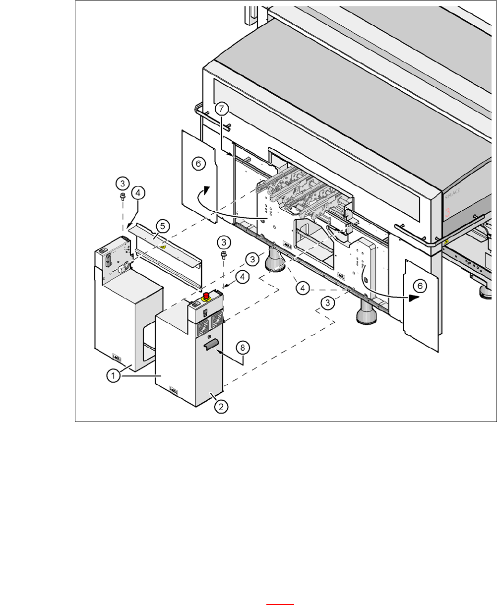
Fig. 4.5 - 8 Install extension kit to the PCB output side
(1) Extension kit
(2) Door
(3) Fillister head screw DIN 912, M6x16 and washer
(4) Grounding connection
(5) Transport cover
(6) Side plate, dismantled
(7) Insert rail
(8) Axis unit CA4 gantries 2 and 3 (CA4)
Remove both side plates (item 6 in fig. 4.5 - 8).
User Manual SIPLACE CA 4 Setting Up and Commissioning
Edition 08/2011 EN 4.5 Setting Up the Placement Machine
281
CAUTION 4
Do not unscrew the three bottom screws straight away. Simply loosen them so that the side
plate does not fall off.
Detach the ground cable from the side plate.
Remove both doors (item 2 in fig. 4.5 - 8) from the extension kit (item 1).
Note: 4
To avoid damage, we recommend that a second person helps to assemble the extension kit.
Place the axis unit (item 8 in fig. 4.5 - 8) down at the side of the placement machine, so that
you have enough room to fit the extension kit (item 1 in fig. 4.5 - 8
).
Make sure that the connecting cables to the axis unit are not too tight.
Lift one half of the extension kit (item 1 in fig. 4.5 - 8) against the machine frame and position
it so that the assembly bracket lies on the assembly bar (item 7 in fig. 4.5 - 8
).
CAUTION 4
Make sure that this half of the extension kit does not collide with the hexagonal shaft of the
PCB conveyor and thus bend the shaft.
Fasten this half of the extension kit with 2 fillister head screws M6x16 and the corresponding
discs (item 3 in fig. 4.5 - 8
).
Before assembling the second half of the extension kit, fit the conveyor covers (item 5 in fig.
4.5 - 8
). The procedure is as follows: