00195941-03-UM SiplaceCA-EN.pdf - 第215页
User Manual SIPLACE CA 3 Technical Data Edition 08/2011 EN 3.11 Controls on the SWS 215 3.1 1 Controls on the SWS Each SWS features a monitor screen and keyboar d. The EMERGENCY STOP butto n is located on one side of the…
3 Technical Data User Manual SIPLACE CA
3.10 Controls on the Placement Machine Edition 08/2011 EN
214
3.10.3.1 Controls on the Operating Fields of the Placement Machine
The two operator panel have identical control functions.
Monitor, keyboard, Start and Stop buttons 3
Both sides of the placement machine feature a monitor screen and keyboard.
The Start and Stop buttons are located beneath the keyboard. The on-screen dialog will occasion-
ally prompt you to activate certain actions using buttons, and this arrangement will make it easier
for you both to activate and to interactively control these actions.
Main switch 3
The main power switch is part of the power module. It is located on the left-hand operator panel
viewed in the direction of PCB transport. It is located here because it is only needed for servicing
and preventive maintenance work and is therefore not subject to frequent use.
3.10.3.2 Controls on the Input and Output Sides of the Placement Machine
The controls on the input and output sides of the placement machine are identical.
EMERGENCY STOP buttons, Start and Stop buttons 3
There is an EMERGENCY STOP button and Start and Stop buttons on both the input and output
sides of the PCB conveyor. This arrangement was adopted for the buttons because it enables
them to be reached quickly and easily from any position.
User Manual SIPLACE CA 3 Technical Data
Edition 08/2011 EN 3.11 Controls on the SWS
215
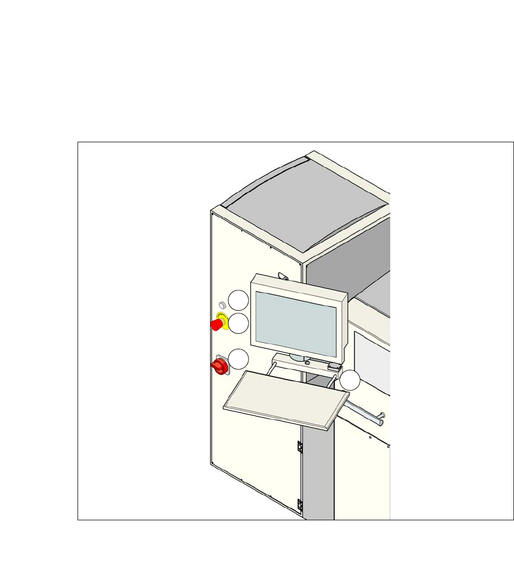
3.11 Controls on the SWS
Each SWS features a monitor screen and keyboard.
The EMERGENCY STOP button is located on one side of the SWS together with the other con-
trols.
3.11.1 Controls and Displays
3
Fig. 3.11 - 1 Controls and displays
(1) Operating status indicator lamp (3) Power supply switch
(2) Emergency STOP switch (4) Monitor screen with keyboard
1
2
3
4

3 Technical Data User Manual SIPLACE CA
3.11 Controls on the SWS Edition 08/2011 EN
216
3.11.2 Description
All the controls can be reached by a 1.40 m tall person.
EMERGENCY STOP button 3
The EMERGENCY STOP button latches in the ON position when pressed. SWS and SIPLACE
switch to EMERGENCY STOP state. The power supply to all axes of the SWS is interrupted. Turn
the button to release it.
WARNING 3
Even when the emergency STOP button is activated, there are still some live voltages present.
Operating status indicator on the SWS 3
The operation status indicator lights up, if the SWS is switched on.
Main switch 3
The main switch is used for switching the power supply to the SWS on and off.
WARNING
Some parts inside the placement machine will still carry potentially lethal voltages, even when
the machine is switched off at the main switch. 3
LCD touchscreen 3
Each SWS features a flat screen monitor with LCD technology and touchscreen function.
Keyboard 3
The keyboard is located beneath the monitor. The keyboard is equipped with a USB port, which
can be used for storing data on an external data storage medium.