00195941-03-UM SiplaceCA-EN.pdf - 第177页
User Manual SIPLACE CA 3 Technical Data Edition 08/2011 EN 3.7 SIPLACE Wafer System (SWS) 177 3 Fig. 3.7 - 27 Modules of the gripper (location 1 and 3) 3 (1) Gripper (2) T oothed belt axis (3) Insertion location for barc…
3 Technical Data User Manual SIPLACE CA
3.7 SIPLACE Wafer System (SWS) Edition 08/2011 EN
176
3
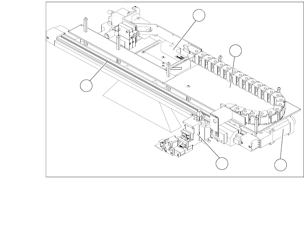
Fig. 3.7 - 26 Modules of the gripper (location 2 and 4)
3
(1) Gripper (2) Toothed belt axis
(3) Insertion location for barcode scanner
(optional)
(4) AD-MOT board below the cover
(5) Motor with coupling
1
4
5
3
2
User Manual SIPLACE CA 3 Technical Data
Edition 08/2011 EN 3.7 SIPLACE Wafer System (SWS)
177
3
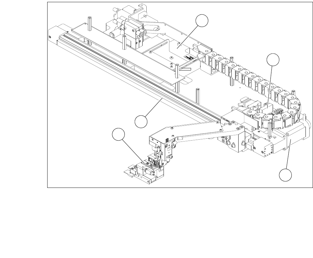
Fig. 3.7 - 27 Modules of the gripper (location 1 and 3)
3
(1) Gripper (2) Toothed belt axis
(3) Insertion location for barcode scanner
(optional)
(4) AD-MOT board
(5) Motor with coupling
1
2
4
5
3
3 Technical Data User Manual SIPLACE CA
3.7 SIPLACE Wafer System (SWS) Edition 08/2011 EN
178
3.7.7 Options
3.7.7.1 Linear Dipping Unit (LDU)
3
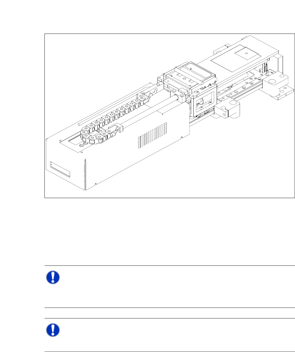
Fig. 3.7 - 28 Linear Dipping Unit (LDU)
The linear dipping unit (LDU, Linear dipping unit) is used frequently, to apply the flux on the die
during the flip chip process. This is necessary in order to ensure the reflow process.
The LDU is able to apply high-precision layers of flux. This flux is made available in a so-called
cavity. The depth of the cavity determines the thickness of the flux layer.
NOTE 3
Basically, the LDU has to be supplied for all types of appropriate flip chip fluxes.
However, Epoxid and solder pastes should only be used after performing in-house tests!
NOTE 3
The LDU cannot be used in conjunction with the die attach unit.