00195941-03-UM SiplaceCA-EN.pdf - 第338页
5 Tasks on the Mach ine User Manual SIPLACE CA 5.2 Tasks on the SWS Edition 08/2011 EN 338 5.2.5 Configuring the Needle s of the Ejection System In the SWS GUI switch to the Ma nual op erations -> W afer han dling v…
User Manual SIPLACE CA 5 Tasks on the Machine
Edition 08/2011 EN 5.2 Tasks on the SWS
337
5.2.3 Refilling the Magazine
Refill the magazine with the wafer frames.The centering notches of the wafers frames must
point to the opening of the magazine.
NOTE 5
When using frame adapters for 5, 6 or 7 inch please take care to use each second slot only.
5.2.4 Inserting Magazines into the Magazine Lift
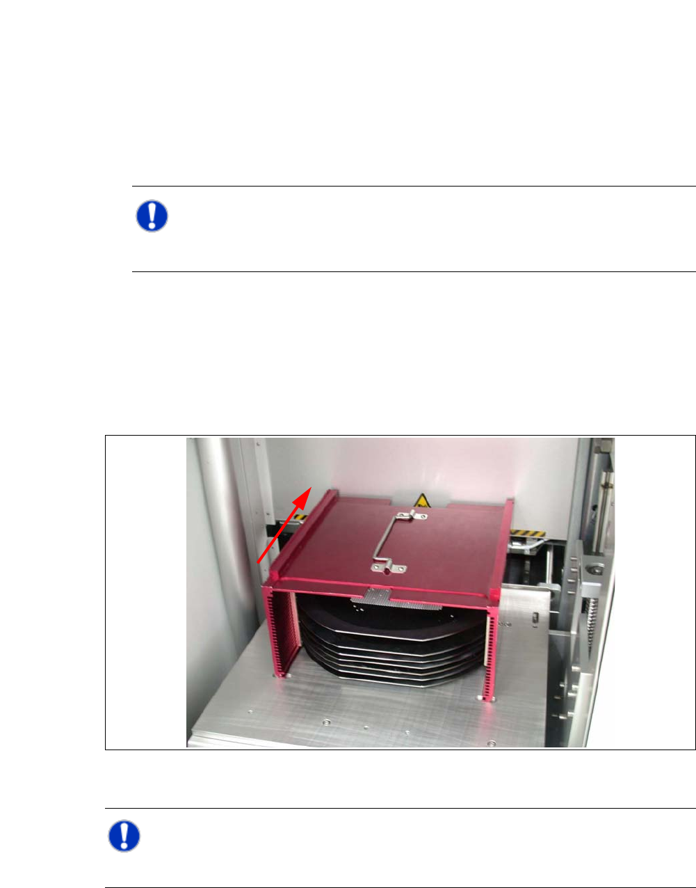
Open the sliding door of the magazine lift and place the magazine onto the plate. The center-
ing notches of the wafers must face the machine. Make sure that the magazine latches prop-
erly.
Fig. 5.2 - 1 Inserting the magazine
NOTE 5
While inserting the wafer frame the recesses of the wafer frame have to lie in feed in direction.
5 Tasks on the Machine User Manual SIPLACE CA
5.2 Tasks on the SWS Edition 08/2011 EN
338
5.2.5 Configuring the Needles of the Ejection System
In the SWS GUI switch to the Manual operations -> Wafer handling view and click the Go
to change position button.
The wafer table is removed.
Switch to the Service -> Galil I/O view and activate the D007 Cylinder DE UP/Down option,
to move the die ejector upwards.
Or
In the SWS GUI switch to the Manual operations -> Die handling view and select the Die
eject system tab.
5
5
Click the button.
The wafer table is removed, the die ejector is moved upwards can be accessed.
5
Switch off the placement machine and the SWS properly.
CAUTION 5
Do not move the wafer table by hand, while the die ejector is in an upward position there is dan-
ger of damage by collision with the wafer table!
User Manual SIPLACE CA 5 Tasks on the Machine
Edition 08/2011 EN 5.2 Tasks on the SWS
339
Open the protective cover above the SWS.
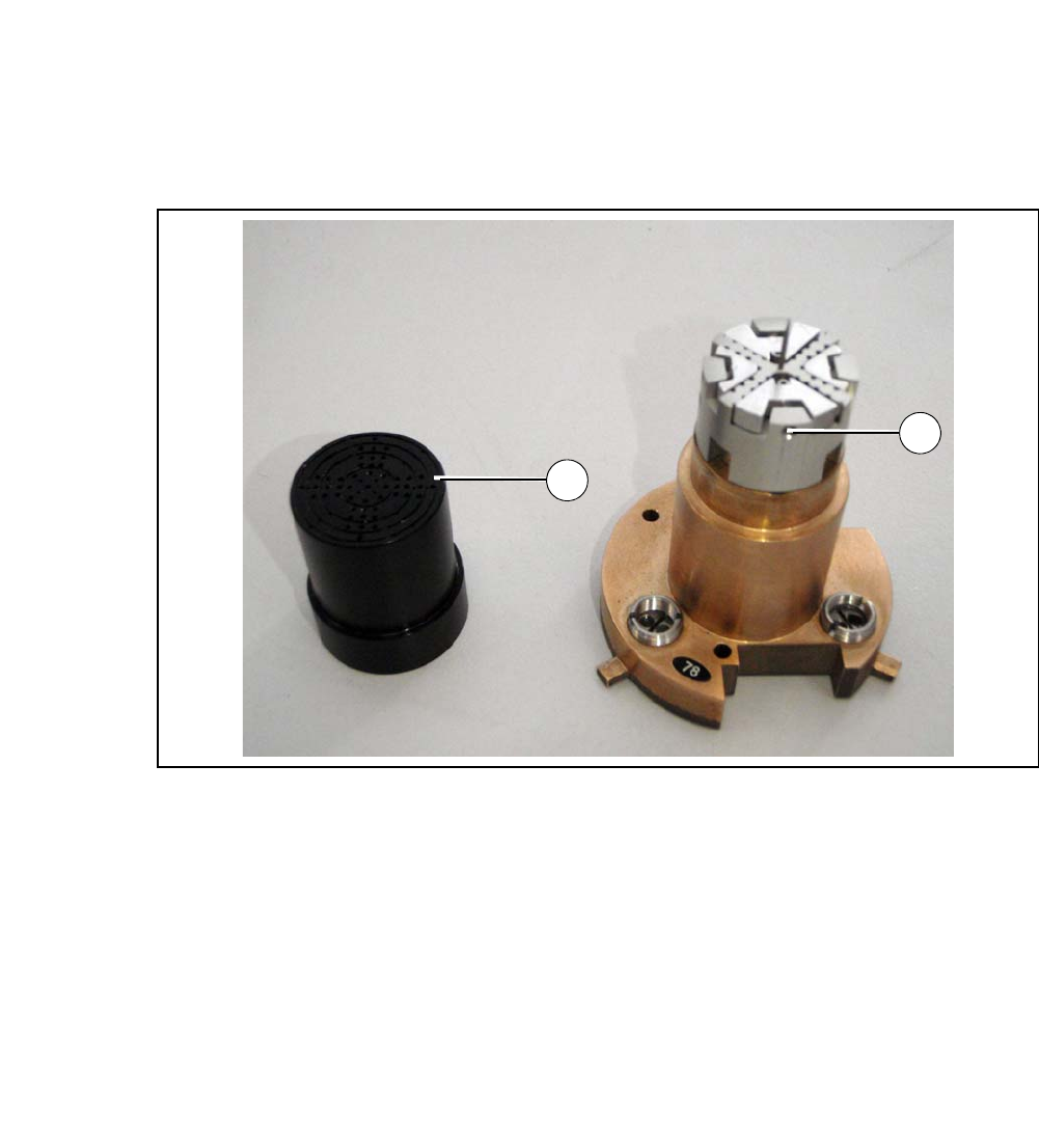
Open the bayonet lock at the centering unit and take the needle kit out.
5
Fig. 5.2 - 2 Needle kit with vacuum cap removed
Legend
5
Remove the vacuum cap from the needle kit (1).
Loosen the grub screw (2).
Insert the appropriate needle matrix for your product.
Insert all needles carefully into the segments and align the needles in about the same line.
Loosely screw in the grub screws. The needles still have to be movable.
Carry out the following adjustments with the relevant calibration standard.
(1) Vacuum cap (2) Grub screw
1
2