00195941-03-UM SiplaceCA-EN.pdf - 第432页
7 Station Enlargements User Manual SIPLACE CA 7.1 Nozzle Changer Edition 08/2011 EN 432 Placing a Nozzle Down 7 – The locking plate (item 2 in fig. 7.1 - 7 ) opens and r eleases the nozzles. – The Z-axis of the Collect&a…
User Manual SIPLACE CA 7 Station Enlargements
Edition 08/2011 EN 7.1 Nozzle Changer
431
Align the nozzle changer so that the sloping side points towards the component trolley dock-
ing unit.
WARNING 7
Only install the associated nozzle changer for each placement head. There is a risk of head
crashes with mixed configurations.
Only use reject bins marked [03003719-06] at locations without SWS. At locations with SWS
only use reject bins marked [03070917-01]. Otherwise there is a risk of collision with the com-
ponent sensor of the C&P20 placement head (see section 2.6.9, page 76).
7.1.2.5 Functional Description
The nozzles are located in nozzle garages and are fixed by a movable locking plate. A pneumatic
cylinder moves the locking plate by 7 mm. Depending on the position of the locking plate, all noz-
zles are either clamped into place or released. The default position of the locking plate, i.e. if there
is no nozzle change in progress, is "closed".
Each magazine on the nozzle changer has two positioning fiducials for detecting the position and
orientation of the magazine. The magazine locations are numbered from 1-6 for the nozzle
changers of "row 1" and from 7-12 for the "row 2" nozzle changers (see fig. 7.1 - 4
). The 12 nozzle
garages in the magazines are also numbered consecutively (see fig. 7.1 - 9
). 7
NOTE 7
Special magazines can be made after consulting with ASM Assembly Systems GmbH & Co.KGa
and receive a seperate marking.
Nozzle Pick Up 7
– The Z-axis of the Collect&Place CA head moves downwards.
– The locking plate (item 2 in fig. 7.1 - 7
) opens and releases the nozzles.
– The nozzle is taken up by the sleeve of the Collect&Place CA head.
– The Z axis moves up.

7 Station Enlargements User Manual SIPLACE CA
7.1 Nozzle Changer Edition 08/2011 EN
432
Placing a Nozzle Down 7
– The locking plate (item 2 in fig. 7.1 - 7) opens and releases the nozzles.
– The Z-axis of the Collect&Place CA head moves downwards and places the nozzle down.
– The locking plate closes.
– The Z-axis of the Collect&Place CA head moves upwards.
Rejecting Defective Nozzles 7
– At the reject unit (item 4 in fig. 7.1 - 4) the Z-axis of the Collect&Place CA head moves down-
wards and transfers the defective nozzle to the reject unit. The nozzle is turned and does not
fit through the opening any longer.
– The Z axis moves up again and the nozzle is stripped from the sleeve opening.
– The nozzle drops into the reject bin.
User Manual SIPLACE CA 7 Station Enlargements
Edition 08/2011 EN 7.1 Nozzle Changer
433
7
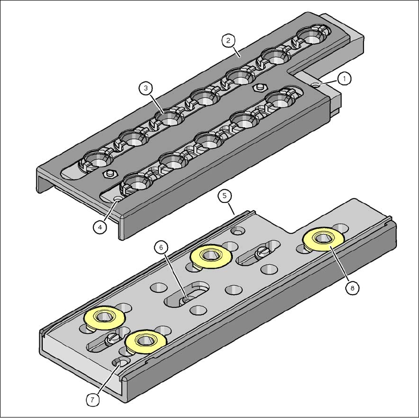
Fig. 7.1 - 7 Magazine and nozzle holders
(1) Fiducial for determining the position
(2) Locking plate in position "magazine open"
(3) Nozzle garage
(4) Fiducial for determining the angular position
(5) Hole for cylinder pin to center the magazine
(6) Hole for cylinder pin of the push mechanism
(7) Longhole for cylinder pin to center the magazine
(8) Pushbutton for engaging the magazine at the nozzle changer