00195941-03-UM SiplaceCA-EN.pdf - 第418页
6 Component and Die Handling User Manual SIPLACE CA 6.5 Docking Station for SIPLACE X Series Component Trolley Edition 08/2011 EN 418 6.5.4 Dimensions for the Docking St at ion with Component T rolley Docked 6 Fig. 6.5 -…
User Manual SIPLACE CA 6 Component and Die Handling
Edition 08/2011 EN 6.5 Docking Station for SIPLACE X Series Component Trolley
417
6
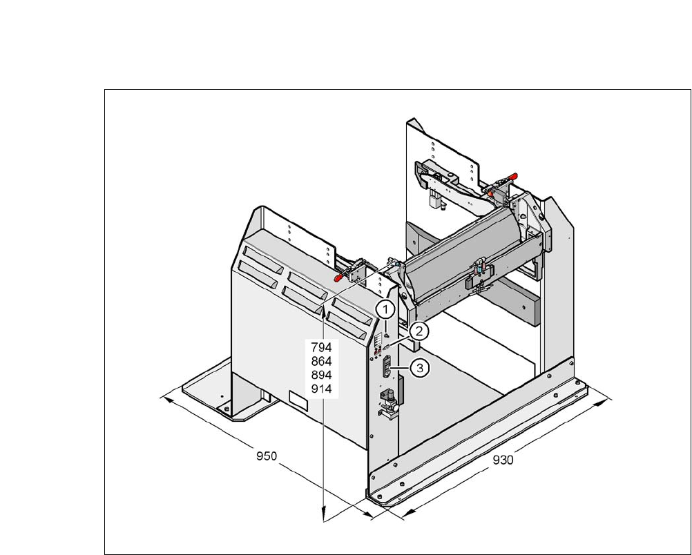
Fig. 6.5 - 2 Docking station - Dimensions in millimeters, connection points
(1) Compressed air connection
(2) CAN bus connection
(3) Power supply connection
6 Component and Die Handling User Manual SIPLACE CA
6.5 Docking Station for SIPLACE X Series Component Trolley Edition 08/2011 EN
418
6.5.4 Dimensions for the Docking Station with Component Trolley Docked
6
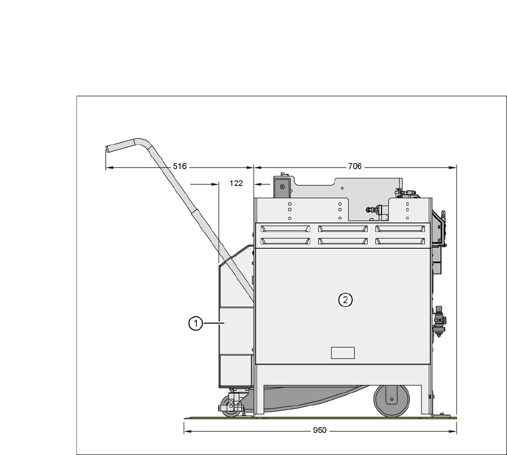
Fig. 6.5 - 3 Docking station with component trolley docked - dimensions in millimeters
(1) Component trolley
(2) Docking station
User Manual SIPLACE CA 6 Component and Die Handling
Edition 08/2011 EN 6.5 Docking Station for SIPLACE X Series Component Trolley
419
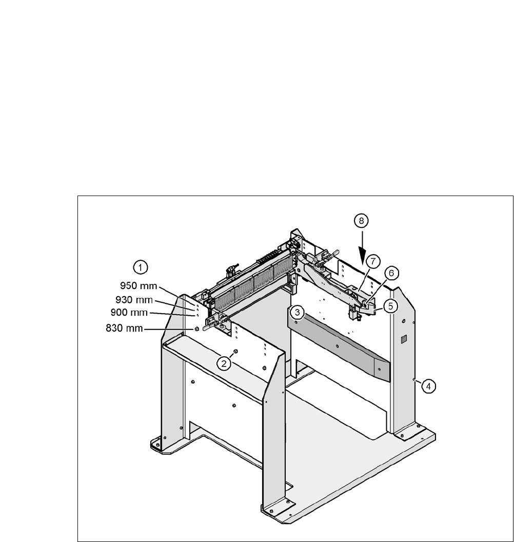
6.5.5 Adapting the Component Trolley Docking Unit to the PCB Conveyor Height
The X-series component trolley docking unit can be set to the following PCB conveyor heights with
just a few simple actions:
830 mm ± 15 mm (standard height)
900 mm ± 15 mm
930 mm ± 15 mm
950 mm ± 15 mm (SMEMA height)
6
Fig. 6.5 - 4 Adapting the component trolley docking unit to the PCB conveyor heights
(1) Holes for the PCB conveyor height
(2) Hexagonal nut M8 and washer, 6x
(3) Hexagon socket head screw M8x40, 6x
(4) Hexagon socket head screw M5x12, 4x
(5) Guide
(6) Hexagon socket head screw M8x18, 2x
(7) Component trolley docking unit
(8) Panel