00195941-03-UM SiplaceCA-EN.pdf - 第436页
7 Station Enlargements User Manual SIPLACE CA 7.1 Nozzle Changer Edition 08/2011 EN 436 NOTE 7 – Mov e the locking plate int o the "Magazine locked" position. – Before inserting it, align the magazine so that t…
User Manual SIPLACE CA 7 Station Enlargements
Edition 08/2011 EN 7.1 Nozzle Changer
435
7
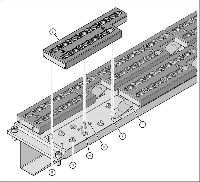
Fig. 7.1 - 8 Changing a magazine
(1) Lever for raising the magazine
(2) Cylinder pin, engages in magazine hole
(3) Spring pin for triggering the microswitch
(4) Pin of the slide mechanism, moves the locking plate
(5) Pushbutton ball fixture
(6) Cylinder pin, engages in magazine longhole
(7) Locking plate in position "magazine locked"
7 Station Enlargements User Manual SIPLACE CA
7.1 Nozzle Changer Edition 08/2011 EN
436
NOTE 7
– Move the locking plate into the "Magazine locked" position.
– Before inserting it, align the magazine so that the centering pins (item 2 and 6 in fig. 7.1 - 8
)
can slide into the centering holes and slot (item 6 in fig. 7.1 - 7).
Position the magazine on the pushbutton ball fixtures (item 5 in fig. 7.1 - 8).
Press the magazine down evenly so that the snap fastener balls engage in all the snap fas-
teners at the same time.
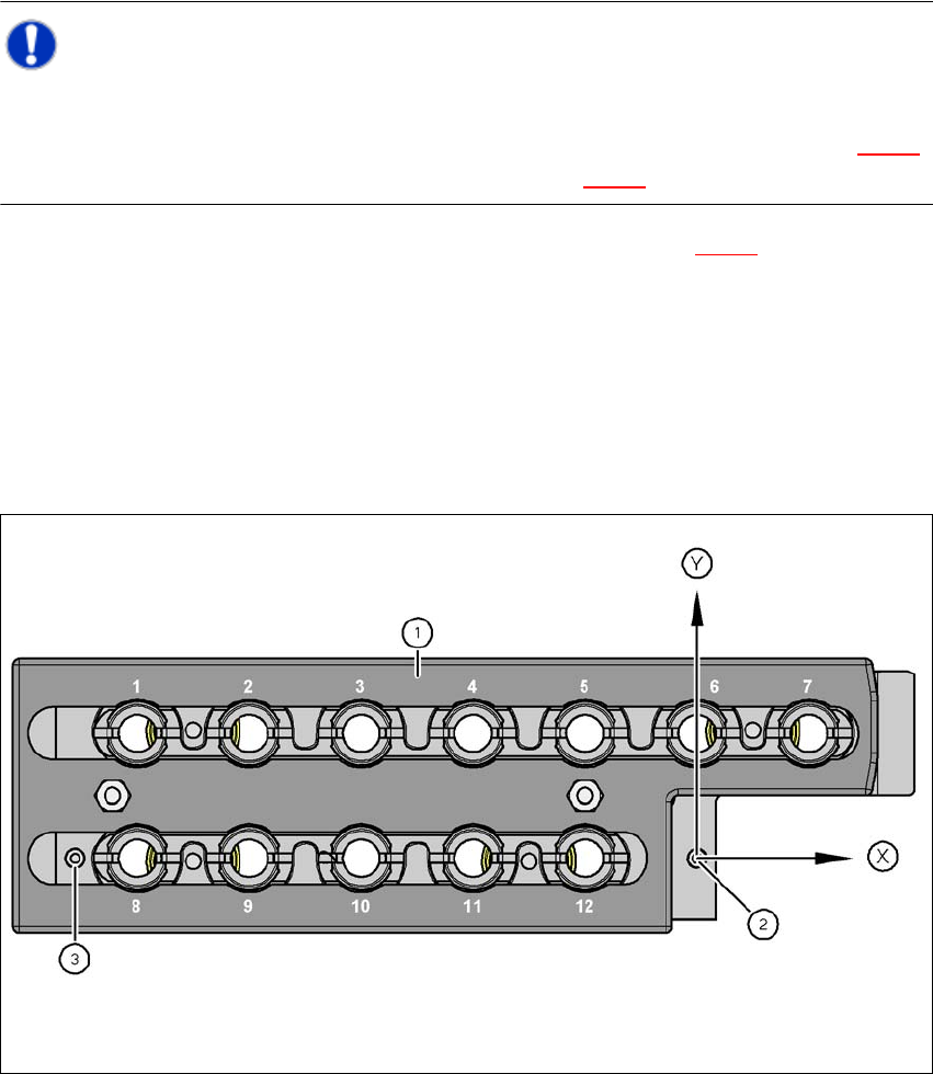
7.1.2.8 Position Detection
Each magazine of the nozzle changer has two fiducials: one for determining the position and one
for determining the angular position.
7
Fig. 7.1 - 9 Nozzle magazine - holder numbering, fiducials for determining the position and angular position
(1) Locking plate in position "magazine open"
(2) Fiducial for determining the position
(3) Fiducial for determining the angular position
User Manual SIPLACE CA 7 Station Enlargements
Edition 08/2011 EN 7.1 Nozzle Changer
437
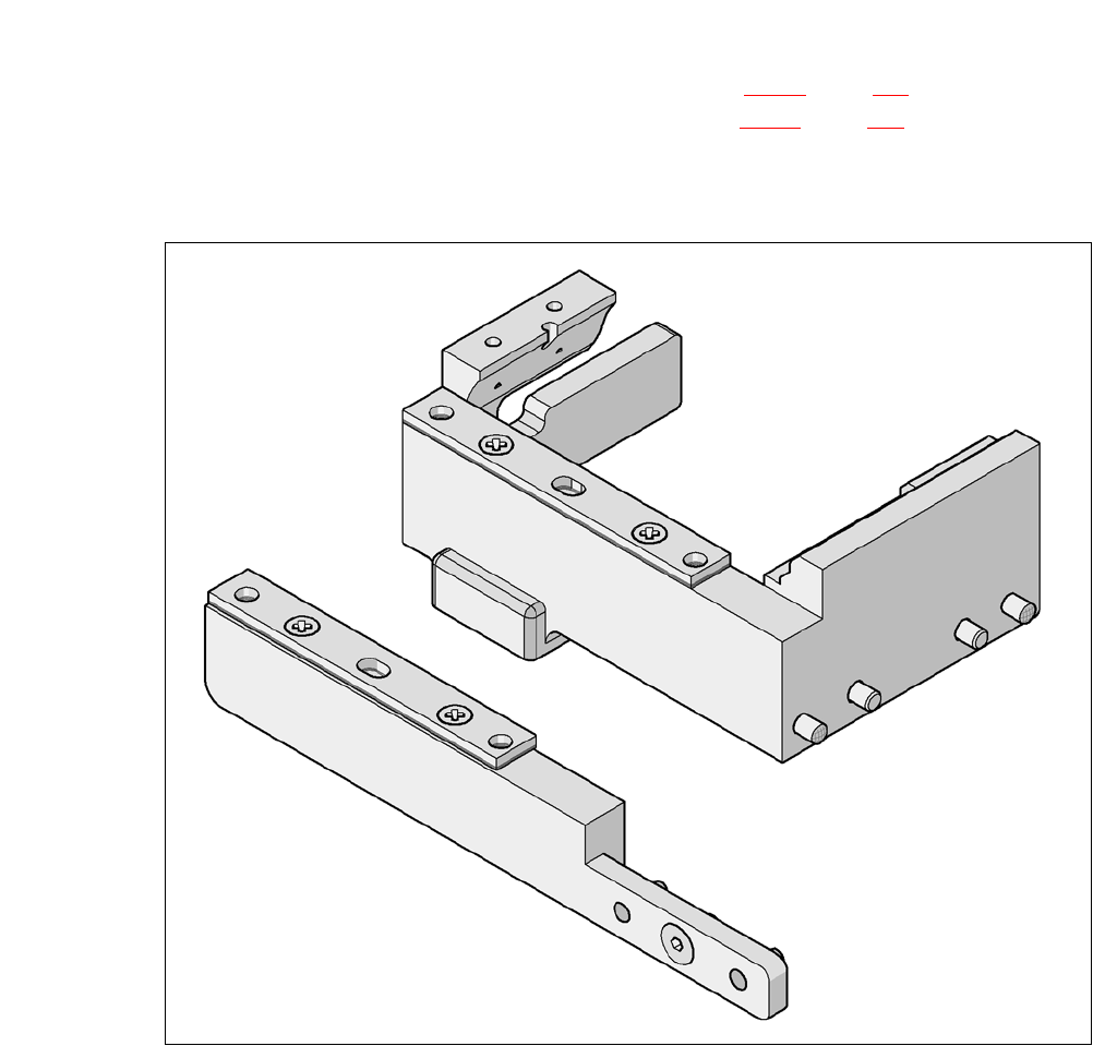
7.1.2.9 Nozzle Changer "Row 2" for the 20 Segment Collect&Place CA Head
[00119716-xx] Nozzle changer 2, X-serie, C&P20
lThe nozzle changer "Row 2" can be installed at the following locations, if no SWS is installed:
CA4 machine: locations 1, 2, 3 and 4 (see fig. 7.1 - 4
, page 428)
CA3 machine: Locations 1, , 3 and 4 (see fig. 7.1 - 5
, page 429)
The retrofit package contains appart from the the nozzle changer an assembly kit.
7
Fig. 7.1 - 10 Assembly kit for the nozzle changer "Row 2"
7
7