00195941-03-UM SiplaceCA-EN.pdf - 第370页
5 Tasks on the Mach ine User Manual SIPLACE CA 5.12 Docking the Component Trolley In or Out Edition 08/2011 EN 370 W ARNING 5 Observe the safety instructions for mo ving the compon ent trolley in section 2.6.7 , page 74 …
User Manual SIPLACE CA 5 Tasks on the Machine
Edition 08/2011 EN 5.12 Docking the Component Trolley In or Out
369
The safety concept for the component trolley changeover prescribes that the user presses a but-
ton (item 1, 2, 3 or 4 in fig. 5.12 - 1
) on the input or output side of the machine, to dock or undock
the component trolley. This ensures that the operator is always standing to the side of the place-
ment machine. In addition, the component trolley can only be docked in if the protective covers
are closed.
5.12.2 Docking Out the Component Trolley
Click on the STOP PROCESSING PCB icon in the MAIN VIEW menu.
The PCB in progress will be completed. The icons of the SINGLE FUNCTIONS menu will
then be activated. 5
Click on the desired icon SINGLE FUNCTIONS GANTRY.
Select GANTRY FUNCTIONS.
From this menu, click on the GO TO SET-UP POSITION button.
All the placement heads will move across the PCB conveyor to prevent them being dam-
aged when the component trolley is changed. 5
Press the appropriate button on the input or output side of the machine (item 1, 2, 3 or 4 in
fig. 5.12 - 1
) until the component trolley is undocked.
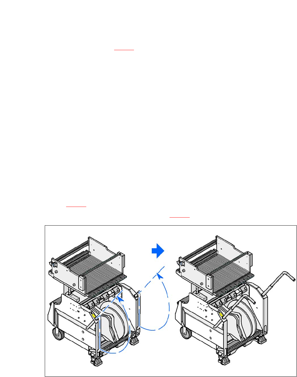
Swing both handles upwards (item 1 in fig. 5.12 - 2).
5
Fig. 5.12 - 2 Component trolley - swivel handles up to push
5
With both hands on the handles, pull the component trolley out of the placement machine.
5 Tasks on the Machine User Manual SIPLACE CA
5.12 Docking the Component Trolley In or Out Edition 08/2011 EN
370
WARNING 5
Observe the safety instructions for moving the component trolley in section 2.6.7, page 74.
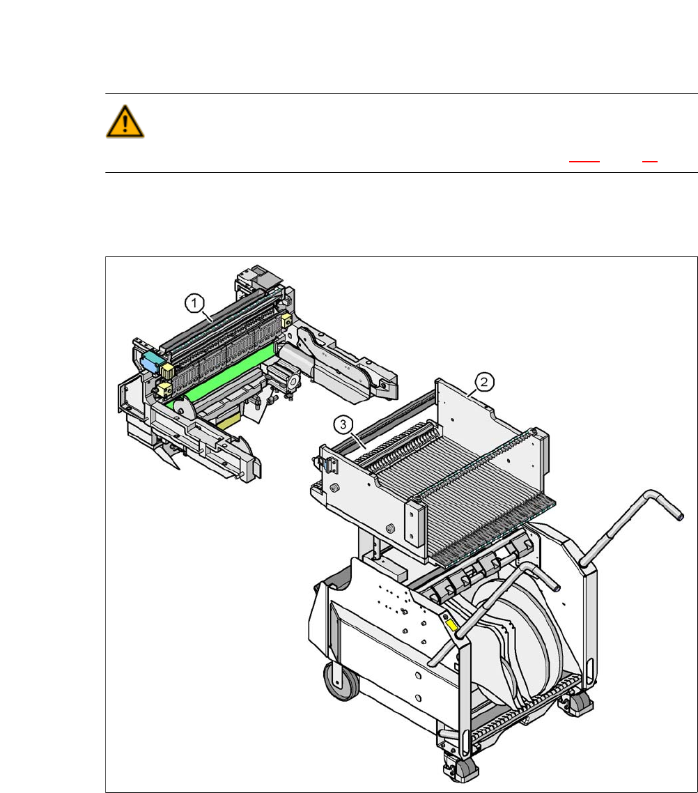
5.12.3 Docking the X Series Component Trolley
5
Fig. 5.12 - 3 Component trolley and component trolley docking unit, SIPLACE X-series
(1) Component trolley docking unit, SIPLACE X-series
(2) Component trolley, SIPLACE X-series
(3) Locking latches

User Manual SIPLACE CA 5 Tasks on the Machine
Edition 08/2011 EN 5.12 Docking the Component Trolley In or Out
371
CAUTION 5
The component trolley may only be docked into its docking unit. Take care when inserting the
component trolley of the SIPLACE X series machine, so that you do not hit any obstacles with
the locking latches (item 3 in fig. 5.12 - 3).
NOTE 5
Cut the component tapes off flush with the front end of the X feeder modules before you dock in
the component trolley.
CAUTION 5
Check that the placement head is outside the range of the component trolley.
Carefully push the component trolley into machine as far as the stop.
NOTE 5
Close the protective covers since the component trolley can only be docked in if the covers are
closed.
Press the appropriate button on the input or output side of the machine (item 1, 2, 3 or 4 in
fig. 5.12 - 1
until the trolley is completely docked.
Push the sleeves (item 1 in fig. 5.12 - 4) on both handles up and swing the handles down (item
2 in fig. 5.12 - 4
).