00195941-03-UM SiplaceCA-EN.pdf - 第310页
4 Setting Up and Commissioning User Manual SIPLACE CA 4.5 Setting Up the Placement Machine Edition 08/2011 EN 310 4.5.13.2 Axis unit CA4, CA3 (Gantries 1 and 4) - connec t Plugs Connect the power cable as shown in the …
User Manual SIPLACE CA 4 Setting Up and Commissioning
Edition 08/2011 EN 4.5 Setting Up the Placement Machine
309
4.5.13 Install Axis Slide In at the CA4 and CA3
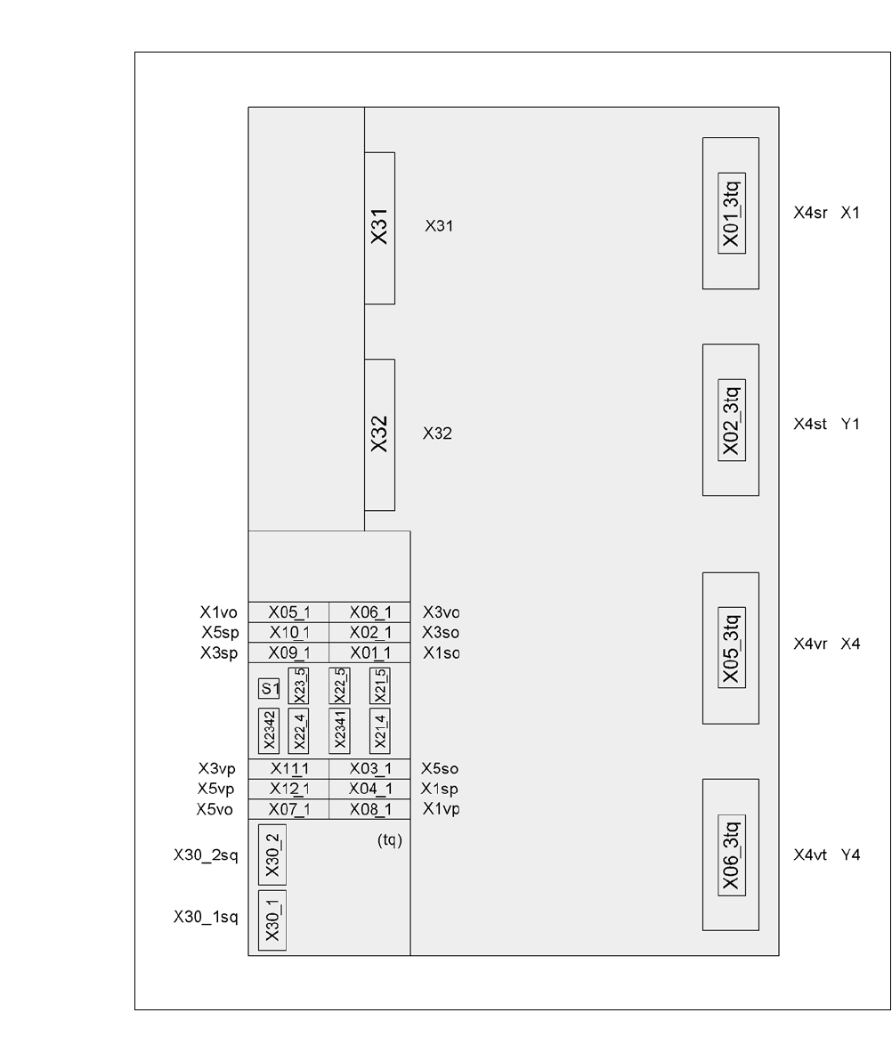
4.5.13.1 Axis unit CA4, CA3 (gantries 1 and 4), electrical connection points
4
Fig. 4.5 - 23 Axis unit CA4, CA3 (gantries 1 and 4), rear side - connect electrical connection points
PlugPlug
Plug

4 Setting Up and Commissioning User Manual SIPLACE CA
4.5 Setting Up the Placement Machine Edition 08/2011 EN
310
4.5.13.2 Axis unit CA4, CA3 (Gantries 1 and 4) - connect Plugs
Connect the power cable as shown in the following diagram:
4
4
Check the switch settings of S1
1: OFF
2: OFF
Axis unit
Gantry 1 and gantry 4
Plug
Connection cable NOTE
Plug Cable
X31
X31 03009762
03009763
03009764
03009765
03009766 W1-W5
Secure connector with clips
X32
X32 03009822
03009823
03009824
03009825
03009827
Secure connector with clips
X01_3tq X4sr 03009760 Snap connector into place
X02_3tq X4st 03009761 Snap connector into place
X05_3tq X4vr 03009820 Snap connector into place
X06_3tq X4vt 03009821 Snap connector into place
X01_1tq
X02_1tq
X03_1tq
X1so
X3so
X5so
03009771
03009772
03009773
Insert as far as the stop
X04_1tq
X09_1tq
X10_1tq
X1sp
X3sp
X5sp
03009774
03009775
03009776
Insert as far as the stop
X05_1tq
X06_1tq
X07_1tq
X1vo
X3vo
X5vo
03009831
03009832
03009833
Insert as far as the stop
X08_1tq
X11_1tq
X12_1tq
X1vp
X3vp
X5vp
03009834
03009835
03009836
Insert as far as the stop
X30_1tq
X30_2tq
X30_1tq
X30_2tq
03010051
03010051
Screw tightly

User Manual SIPLACE CA 4 Setting Up and Commissioning
Edition 08/2011 EN 4.5 Setting Up the Placement Machine
311
4.5.13.3 Assemble Axis unit CA4, CA3 (Gantries 1 and 4)
Carefully lift the axis unit onto the rail in the extension kit.
Make sure that you do not squash any cables.
Push the axis unit into the extension kit as far as the stop.
Secure the axis unit with the fillister head screw.
Insert the cover.
Fasten the ground cable to the door (item 2 in fig. 4.5 - 15, page 293), as shown in fig. 4.5 -
17 on page 297.
Lock the doors.
4.5.13.4 Fitting the Side Plates
Fasten the ground cable to each side plate (item 6 in fig. 4.5 - 15, page 293), as shown in fig.
4.5 - 17
, page 297.
Fix the side plate to the machine frame with 6 fillister head screws.
4.5.14 Fitting the Main Fault Indicator
Connect the main fault indicator cables to the cables on the basic machine.
Insert the main fault indicator into the drilling (item 2 in fig. 4.5 - 24, page 312) until the tube
of the main fault indicator protrudes sufficiently into the clamp below.
Tighten the hexagon socket-head screw under the drilling (item 3 in fig. 4.5 - 24, page 312).