00195941-03-UM SiplaceCA-EN.pdf - 第340页
5 Tasks on the Mach ine User Manual SIPLACE CA 5.2 Tasks on the SWS Edition 08/2011 EN 340 5.2.5.1 Adjust Needles with Calibration S tandard 0308019 1-xx Equipment – Needles as spar e part s – Calibration st andard for t…
User Manual SIPLACE CA 5 Tasks on the Machine
Edition 08/2011 EN 5.2 Tasks on the SWS
339
Open the protective cover above the SWS.
Open the bayonet lock at the centering unit and take the needle kit out.
5
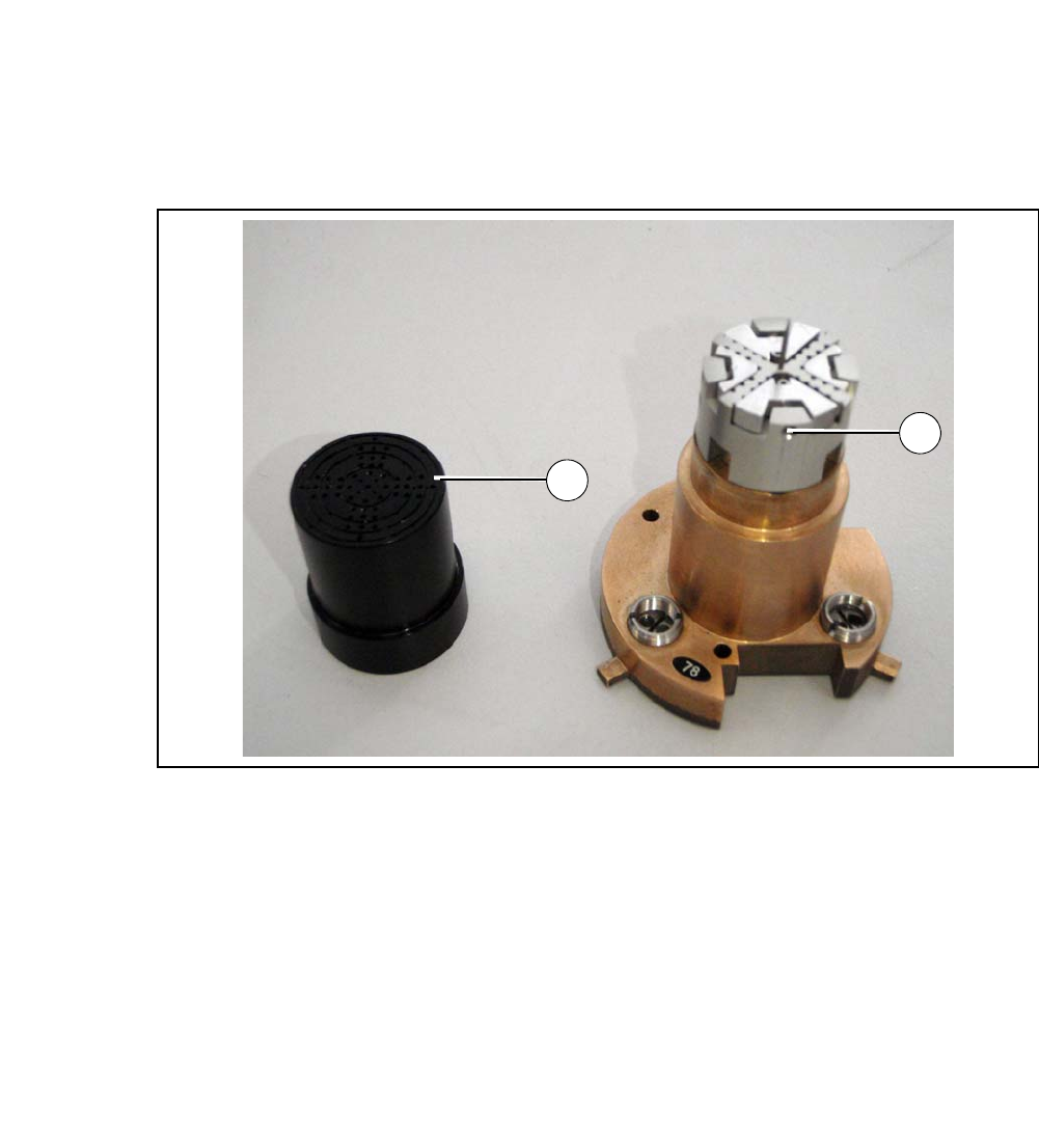
Fig. 5.2 - 2 Needle kit with vacuum cap removed
Legend
5
Remove the vacuum cap from the needle kit (1).
Loosen the grub screw (2).
Insert the appropriate needle matrix for your product.
Insert all needles carefully into the segments and align the needles in about the same line.
Loosely screw in the grub screws. The needles still have to be movable.
Carry out the following adjustments with the relevant calibration standard.
(1) Vacuum cap (2) Grub screw
1
2
5 Tasks on the Machine User Manual SIPLACE CA
5.2 Tasks on the SWS Edition 08/2011 EN
340
5.2.5.1 Adjust Needles with Calibration Standard 03080191-xx
Equipment
– Needles as spare parts
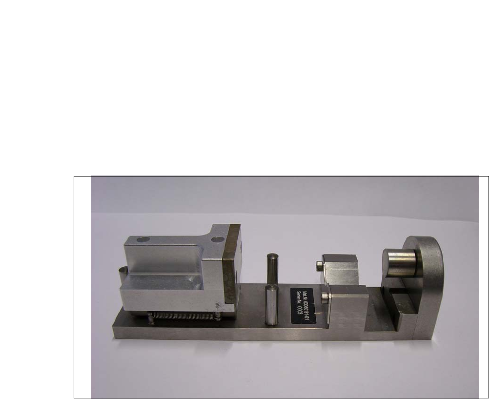
– Calibration standard for the die-ejector (03080191-xx)
With the help of the calibration standard for the die ejector all needles are adjusted into
a defined height and common level. 5
5
Fig. 5.2 - 3 Calibration standard for die-ejector - Item number 03080191-xx
User Manual SIPLACE CA 5 Tasks on the Machine
Edition 08/2011 EN 5.2 Tasks on the SWS
341
5
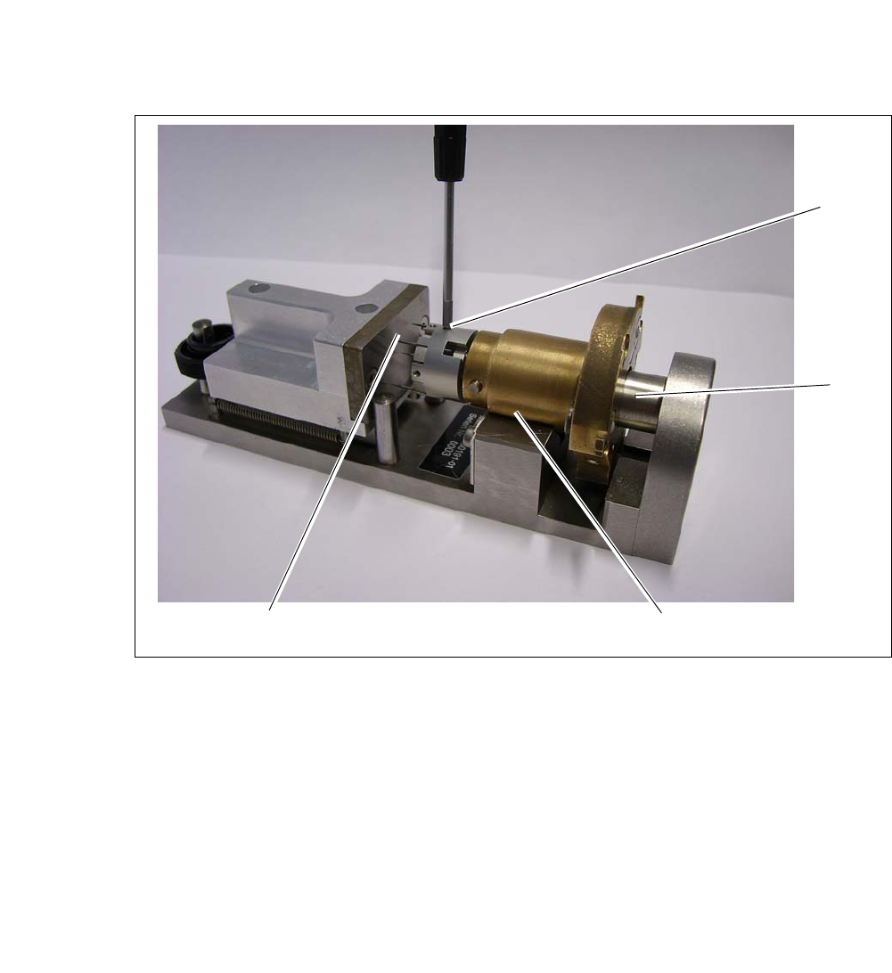
Fig. 5.2 - 4 Calibration standard for die-ejector
Insert the needle unit into the calibration standard for the die-ejector (1). During that the cen-
tering bolt (5) is inserted into the opening on the underside of the ejection unit.
Draw back the ejection unit until it lies fully in the prism. After releasing the crank at the ejec-
tion unit should now be pressed into a defined position against the limiter plate.
Move the alignment plate (2) towards the not clamped needles.
Move the alignment plate as far as the stop against the bolts, so the needles are adjusted by
the plate in one defined height.
Carefully screw in the grub screws (3) (approx. 10Ncm).
Make sure that no needles slipped. In case loosen the screws again and repeat the process.
1
5
2
3