00195941-03-UM SiplaceCA-EN.pdf - 第327页
User Manual SIPLACE CA 4 Setting Up and Commissioning Edition 08/2011 EN 4.6 Installing the SWS 327 4.6.4 Removing the T ransp ort ation Locks – Remove all transpor t locks: – Flip rotary axis – W afer table (X/Y axis) –…
4 Setting Up and Commissioning User Manual SIPLACE CA
4.6 Installing the SWS Edition 08/2011 EN
326
4
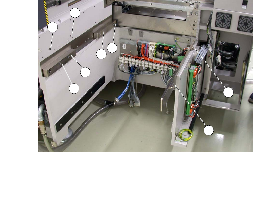
Fig. 4.6 - 4 Picture showing the position of screws for the SWS at the SIPLACE location
You can now remove the fork-lift truck or hand-lift.
(1) M8 (2) M8
(3)Fitting screw (4)M6
(5) M6 (6) M8 for clamping claw
(7) M6 for angle bracket (8) M6 for angle bracket
2
3
5
4
1
7
8
6
User Manual SIPLACE CA 4 Setting Up and Commissioning
Edition 08/2011 EN 4.6 Installing the SWS
327
4.6.4 Removing the Transportation Locks
– Remove all transport locks:
– Flip rotary axis
– Wafer table (X/Y axis)
– Wafer changer feed axis (if present)
4.6.5 Removing the Corrosion Protection from the Guide Rails
Check whether the SWS has been treated with corrosion protection agent. This must be removed
before setting up the SWS.
CAUTION 4
– You should therefore remove the corrosion protection from all the axes and bearings when
you traverse the machine axes for the first time during commissioning.
– Grease all the axes and bearings with the grease described in the maintenance instructions.
If the corrosion protection agent is mixed with the bearing grease on the axes this can greatly re-
duce the service life of the bearings and guide rails.
CAUTION 4
Do not allow any alcohol to enter the guide carriages when you clean the guide rails and scale
rods. Alcohol will damage the bearing grease in the guide carriages.
4.6.6 Power Supply
After performing final adjustment, connect the SWS to the power supply.
4 Setting Up and Commissioning User Manual SIPLACE CA
4.7 Adapting the SIPLACE X-Series Component Trolley to the PCB Conveyor Height Edition 08/2011 EN
328
4.7 Adapting the SIPLACE X-Series Component Trol-
ley to the PCB Conveyor Height
The component trolley for the X feeder modules can be set to the following PCB conveyor heights
with just a few simple actions:
830 mm ± 15 mm (standard height), 900 mm ± 15 mm, 930 mm ± 15 mm,
950 mm ± 15 mm (SMEMA height) 4
4
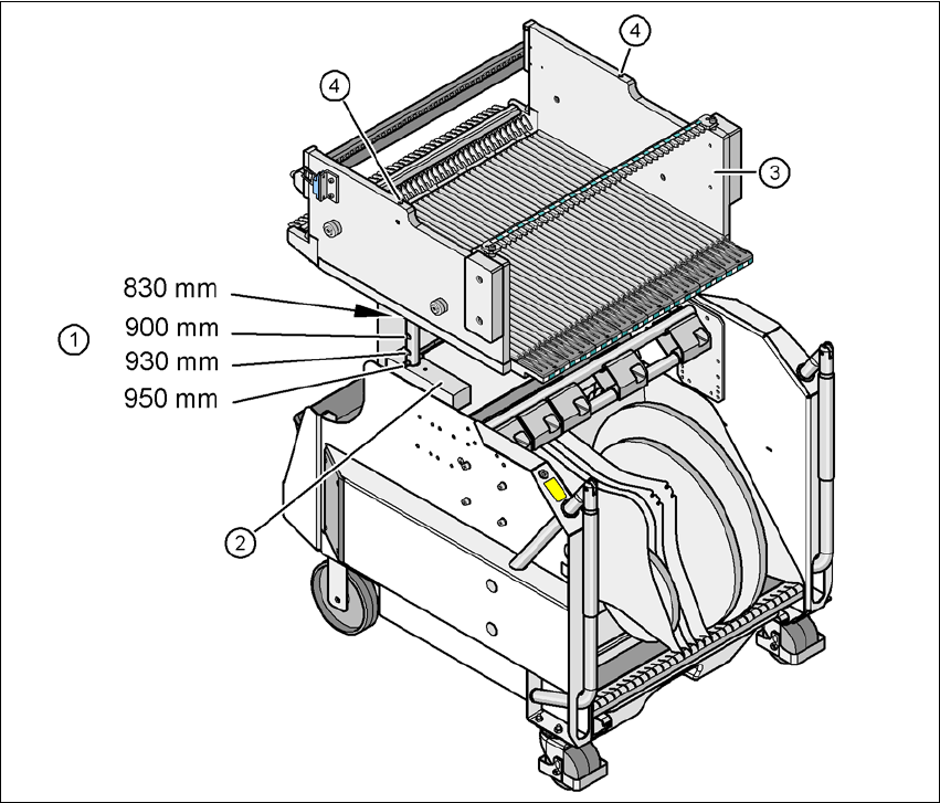
Fig. 4.7 - 1 Component trolley (SIPLACE X-series) with a PCB conveyor height of 950 mm
(1) Holes in the guide columns for the conveyor heights of 900, 930 and 950 mm.
If the conveyor height is 830 mm, the component table lies on the block (2).
(2) Block
(3) Component table
(4) M8 holes for fixing the assembly guide