00195941-03-UM SiplaceCA-EN.pdf - 第484页
7 Station Enlargements User Manual SIPLACE CA 7.13 Coplanarity Laser Module Edition 08/2011 EN 484 7 Fig. 7.13 - 4 Coplanarity laser module (1) Laser sensor (2) Detector (3) Laser e mitter (4) Assembly bracket (5) Contro…
User Manual SIPLACE CA 7 Station Enlargements
Edition 08/2011 EN 7.13 Coplanarity Laser Module
483
7
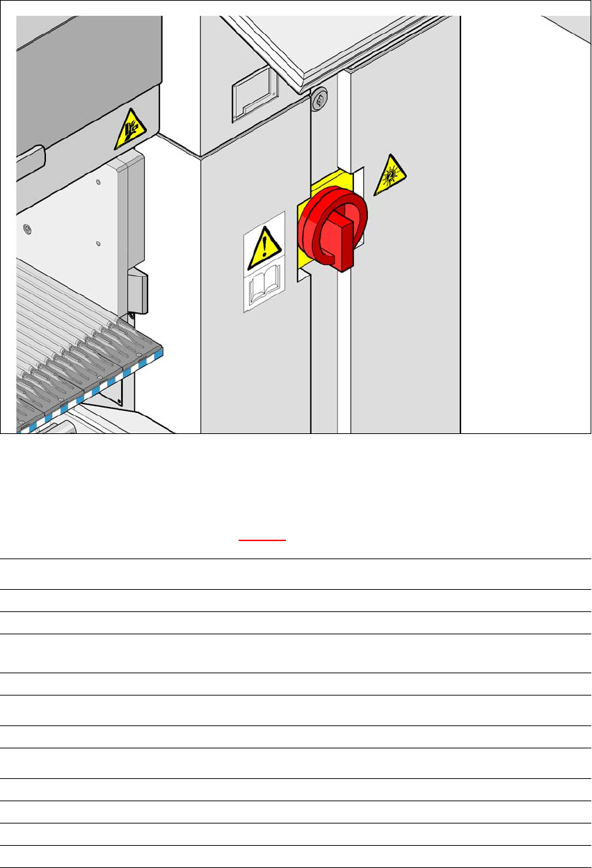
Fig. 7.13 - 3 Warning label W216 beside the main switch
7.13.4 LED Displays on the Controller
The statuses of the coplanarity module are indicated by LEDs. The LED is located on the under-
side of the controller (see item 6 in fig. 7.13 - 4
).
LED state Status display
Green Test object in measuring range
Yellow Measuring range center
Red
Outside the measuring range,
with low reflection
LED Off Laser switched off
LED Power Status display
LED lights up Supply voltage present
LED avg avg1 avg2
Off Off No averaging
Red Off Averaging 1
Off Red Averaging 2
Red Red Averaging 3
7 Station Enlargements User Manual SIPLACE CA
7.13 Coplanarity Laser Module Edition 08/2011 EN
484
7
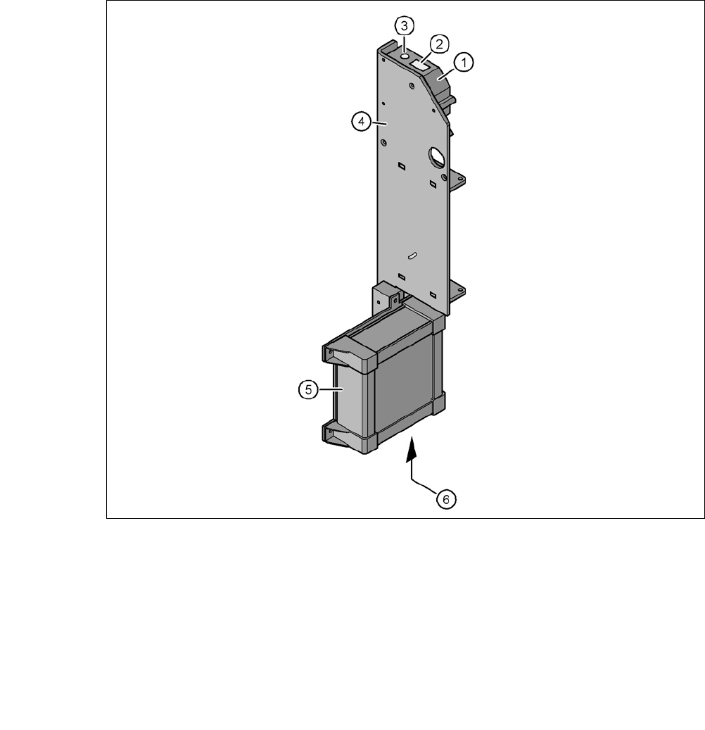
Fig. 7.13 - 4 Coplanarity laser module
(1) Laser sensor
(2) Detector
(3) Laser emitter
(4) Assembly bracket
(5) Controller
(6) LED displays, connections on the controller
User Manual SIPLACE CA 7 Station Enlargements
Edition 08/2011 EN 7.14 Vision Teach Station
485
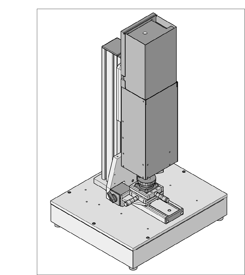
7.14 Vision Teach Station
[00119788-xx] Vision teach station
7
Fig. 7.14 - 1 Vision teach station with component camera, type 33