00195941-03-UM SiplaceCA-EN.pdf - 第289页
User Manual SIPLACE CA 4 Setting Up and Commissioning Edition 08/2011 EN 4.5 Setting Up the Placement Machine 289 4.5.8.4 Axis Slide In CA3 (Gantry 3) - Con necting Plugs Connect the power cabl e as shown in the follow…
4 Setting Up and Commissioning User Manual SIPLACE CA
4.5 Setting Up the Placement Machine Edition 08/2011 EN
288
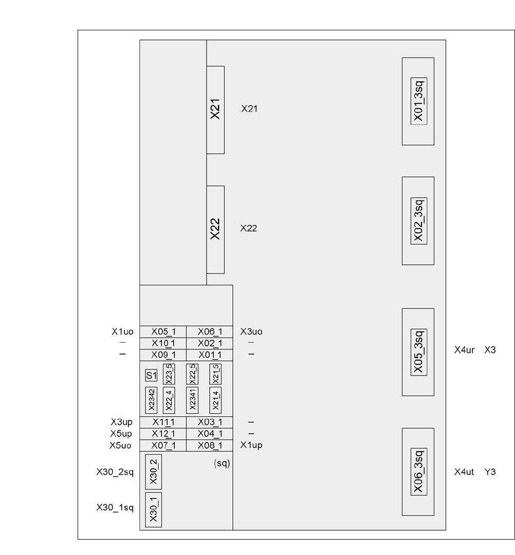
4.5.8.3 Axis Slide In CA3 (Gantry 3) - Electrical Connection Points
4
Fig. 4.5 - 13 Axis unit CA3 (gantry 3), rear side - electrical connection points
Plug
Plug Plug

User Manual SIPLACE CA 4 Setting Up and Commissioning
Edition 08/2011 EN 4.5 Setting Up the Placement Machine
289
4.5.8.4 Axis Slide In CA3 (Gantry 3) - Connecting Plugs
Connect the power cable as shown in the following diagram:
4
4
Check the switch settings of S1
1: ON
2: ON
Continue with section 4.5.8.5 "Fitting the Axis Unit", page 290.
Axis Slide In CA3
(Gantry 3
) - Plug
Connection cable NOTE
Plug Cable
X21 X21
03009782
03009783
03009784
03009785
03009786 W1-W5
Secure connector with clips
X22 X22
03009802
03009803
03009804
03009805
03009807
Secure connector with clips
X05_3sq X4ur 03009800 Snap connector into place
X06_3sq X4ut 03009801 Snap connector into place
X05_1sq
X06_1sq
X07_1sq
X1uo
X3uo
X5uo
03009811
03009812
03009813
Insert as far as the stop
X08_1sq
X11_1sq
X12_1sq
X1up
X3up
X5up
03009814
03009815
03009816
Insert as far as the stop
X30_1sq
X30_2sq
X30_1sq
X30_2sq
03010054
03010054
Screw tightly

4 Setting Up and Commissioning User Manual SIPLACE CA
4.5 Setting Up the Placement Machine Edition 08/2011 EN
290
4.5.8.5 Fitting the Axis Unit
Carefully lift the axis unit onto the rail in the extension kit.
Make sure that you do not squash any cables.
Push the axis unit into the extension kit as far as the stop.
Secure the axis unit with the fillister head screw.
Insert the cover.
Fasten the ground cable to the door (item 2 in fig. 4.5 - 8, page 280), as shown in fig. 4.5 - 10
on page 284
.
Lock the doors.
4.5.8.6 Fitting the Side Plates
Fasten the ground cable to each side plate (item 6 in fig. 4.5 - 8, page 280), as shown in fig.
4.5 - 10
, page 284.
Fix the side plate to the machine frame with 6 fillister head screws.
NOTE 4
If the input conveyor has been dismantled , continue with section 4.5.9
" Fitting the Input Con-
veyor" on page 291.
If the input conveyor is fitted, continue assembly work with section 4.5.14
"Fitting the Main Fault
Indicator" on page 311.