00195941-03-UM SiplaceCA-EN.pdf - 第224页
3 Technical Data User Manual SIPLACE CA 3.13 Vision Cameras Edition 08/2011 EN 224 3.13.1 Assembly Positions for the S t ationary Cameras - IC Camera and FC Camera 3.13.1.1 IC and FC Cameras on the CA4 Machines 3 Fig. 3.…

User Manual SIPLACE CA 3 Technical Data
Edition 08/2011 EN 3.13 Vision Cameras
223
3.13 Vision Cameras
Each Collect&Place CA head has an integrated component camera (see fig. 3.8 - 4 page 186, fig.
3.8 - 7
page 195 and fig. 3.8 - 10 page 200). The stationary P&P component vision camera (type
33) 55 x 45 digital for the TwinHead is permanently fixed to the machine frame.
The component vision module is used to determine:
– the precise position of the components at the nozzle and
– the geometry of the package form.
The PCB cameras are fixed to the bottom of the gantries. They use fiducials on the feeder mod-
ules to determine the exact pickup position of components, which is particularly important for
small components.
The PCB vision module uses fiducials on the PCBs to determine:
– the position of the PCB,
– its rotation angle
– and the PCB skew.
WARNING
RISK OF HEAD CRASH 3
During a placement head change from TwinHead to Collect&Place CA head, the component
camera, stationary, P&P (type 33) 55 x 45, digital, and the component camera, stationary, P&P
(type 25) 16 x 16, digital (FC camera) for the TwinHead must be dismantled, otherwise the Col-
lect&Place CA head will collide with the camera housings.
3 Technical Data User Manual SIPLACE CA
3.13 Vision Cameras Edition 08/2011 EN
224
3.13.1 Assembly Positions for the Stationary Cameras - IC Camera and FC Camera
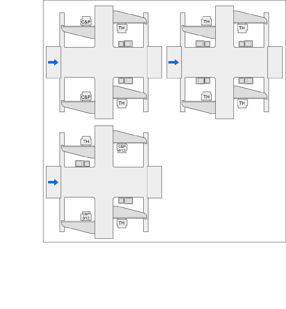
3.13.1.1 IC and FC Cameras on the CA4 Machines
3
Fig. 3.13 - 1 IC and FC Cameras on the CA4 Machines
C&P C&P20CA, C&P12CA or C&P6CA
C&P6/12 6 segment Collect&Place CA head or 12 segment Collect&Place CA head
TH TwinHead
25 FC camera, type 25
33 IC camera, type 33
P1, P2, P3, P4 gantry 1, gantry 2, gantry 3, gantry 4
33 and 25
25 and 33
25 or 33 33 or 25
33 or 25
25 or 33
25 or 33
G3
G3
G4
G4
G1
G2
G2
G1
G4
G3
G2
G1
25 or 33
User Manual SIPLACE CA 3 Technical Data
Edition 08/2011 EN 3.13 Vision Cameras
225
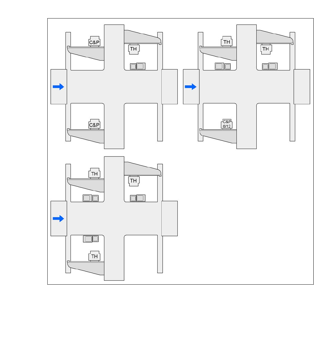
3.13.1.2 IC and FC Cameras on the CA3 Machines
3
Fig. 3.13 - 2 IC and FC Cameras on the CA3 Machines
C&P C&P20CA, C&P12CA or C&P6CA
C&P6/12 6 segment Collect&Place CA head or 12 segment Collect&Place CA head
TH TwinHead
25 FC camera, type 25
33 IC camera, type 33
P1, P2, P3, P4 gantry 1, gantry 3, gantry 4, gantry
33 or 25
25 and 33
25 and 33 33 and 25 25 and 33
33 or 25
G3 G3
G4
G4
G1
G1
G4
G3
G1