00195941-03-UM SiplaceCA-EN.pdf - 第197页
User Manual SIPLACE CA 3 Technical Data Edition 08/2011 EN 3.8 Placement Heads 197 3 Fig. 3.8 - 8 Functional description The star r otates abou t the star axis with its 12 segment s. The segments hold the slee ves. There…

3 Technical Data User Manual SIPLACE CA
3.8 Placement Heads Edition 08/2011 EN
196
In contrast to conventional chip shooters, the twelve nozzles on the SIPLACE Collect&Place CA
heads rotate around a horizontal axis. This not only saves space: the shorter diameter reduces
the centrifugal forces significantly. This means that the danger of component slip during the trans-
port is largely ruled out.
An additional benefit: the Collect&Place CA head cycle times are the same for all components,
which means that the placement rate is not dependent on the component size.
3.8.4.2 Control and Self-Learning Functions
Control and self-learning functions enhance the reliability of the 12 segment Collect&Place CA
head.
– The vertical axis (Z axis) for picking up and placing the component works in sensor stop
mode, in which differences in height during pickup and any unevenness of the PCB surface
are compensated during placement. The average of the deviations during the last 10 place-
ment operations is also taken into account when adapting the further stroke and placement
speeds. The programmed placement force always remains constant.
– Vacuum checks at the nozzles indicate whether the component was picked up or set down
correctly.
– To further increase placement reliability, a component sensor can be installed on the C&PCA
head. The component sensor checks the edge ratio of the components, in addition to whether
the component is present at the nozzle. In this way it is possible to determine whether the
component was picked up by the nozzle transversely or on edge.
– The package form is also checked, and the component is not placed if the geometric data thus
determined differs from the programmed data.
– A digital component camera on the placement head determines the precise position of each
component at the nozzle. With the standard camera modules of the size 0,5 mm x 0,5 mm up
to 18,7 mm x 18,7 mm can beoptical centered. Variations of the transfer position are cor-
rected already before placing. When a component is picked up, the average of the deviations
for the last 10 placement operations is taken into account. This further increases the pickup
accuracy.
– With the help of an optional, high resolution C&P component camera the 12 segment-
Collect&Place-CA-head can optically center and place modules of the size 0,4 mm x 0,2 mm
up to 18,7 mm x 18,7 mm . When placing high speed, flip chip and bare die -components, this
high-resolution digital camera optimizes both the speed and the accuracy. The values can be
found in the table on page 198
.
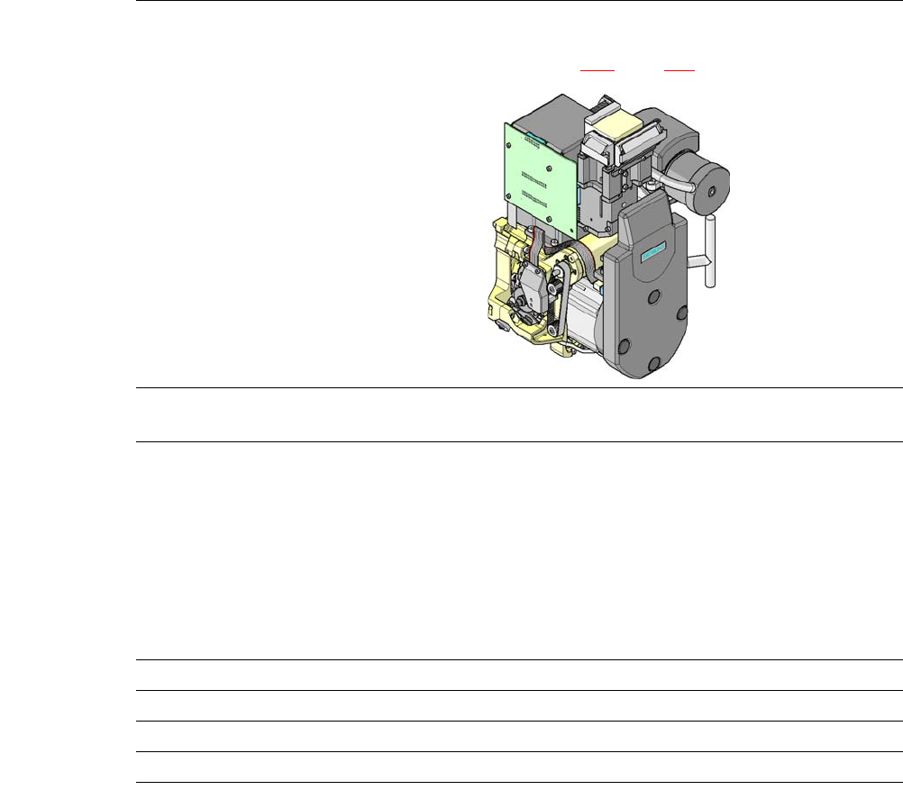
3.8.4.3 Functional Description
The 12 segment Collect&Place CA head consists of three axes, the DR or star axis, the Z-axis
and the DP axis.
User Manual SIPLACE CA 3 Technical Data
Edition 08/2011 EN 3.8 Placement Heads
197
3
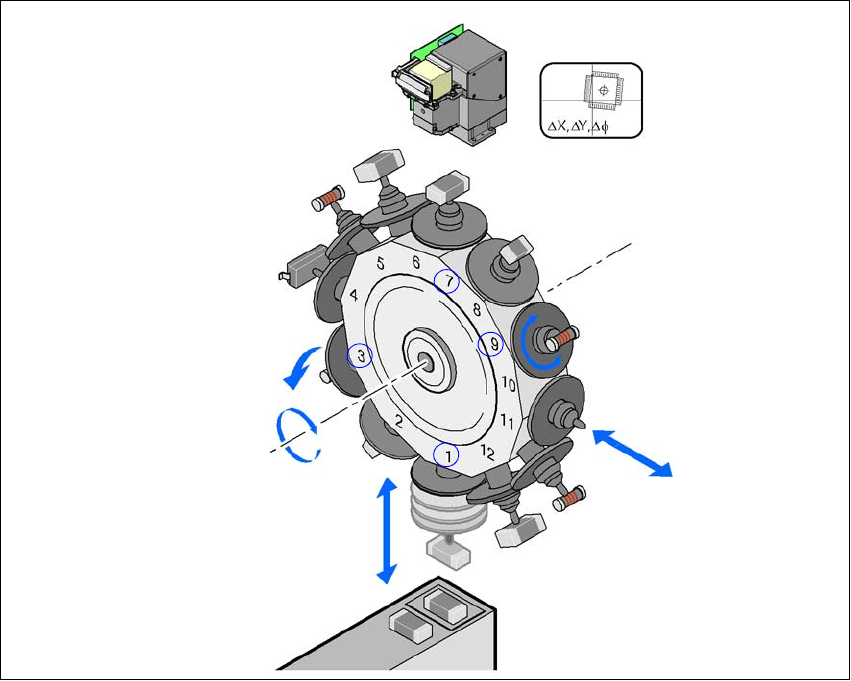
Fig. 3.8 - 8 Functional description
The star rotates about the star axis with its 12 segments. The segments hold the sleeves. There
is a nozzle seated on every sleeve, which sucks up the components, and transports them from
the pickup/placement position (1) to the reject position (3), to the optical centering position (7) or
to the turning position (9).
The Z axis performs a vertical movement. Every sleeve that is in the bottom star position (1) is
raised or lowered by this axis, thus picking up the components from the feeder modules and set-
ting them down on the PCB. The Z axis is an "intelligent axis". It "notes" the pickup height of each
feeder module track and the placement height for each component. This can speed up the place-
ment process. The programmed placement force remains constant.
The DP axis rotates the optically centered component to the desired placement angle.
The sequences of movements of the rotation and translation axes are controlled by control cir-
cuits. Position and speed sensors send the actual values for the axis movement to the axis control.
The nominal and actual values are compared and used to determine the force and speed param-
eters for the servo amplifier, and thus the axis movement to be performed. -The vacuum values
at the nozzle are constantly checked throughout the entire pickup and placement process in order
to keep the placement error rate as low as possible.
Component camera
DP axis
Rotate component
into placement position
Remove or insert sleeve
Z axis
Pick up component
or place it
Star axis
Star rotation
Reject component
3 Technical Data User Manual SIPLACE CA
3.8 Placement Heads Edition 08/2011 EN
198
3.8.4.4 Technical Data
3
12 segment Collect&Place CA head with high-resolution
component camera, type 29, 27 x 27, digital
(see section
7.12, page 478)
Range of components
a
a) Please note that the component range that can be placed is also affected by the pad geometry, the customer-spe-
cific standards and the packaging tolerances.
0201
b
to flip chip, bare die, PLCC44, BGA, µBGA, TSOP,
QFP, SO to SO32, DRAM
b) With 0201 package
Component specifications
Maximum height
Min. lead pitch
Min. lead width
Min. ball pitch
Min. ball diameter
Min. dimensions
Maximum dimensions
Max. weight
6 mm
0.3 mm
0.15 mm
0.13 mm
0.08 mm
0,6 mm x 0,3 mm
18,7 mm x 18,7 mm
2 g
Nozzle types 9 xx
X/Y accuracy (SMD) ± 41 µm/3± 55 µm/4
X/Y accuracy (CA) ± 25 µm/3, ± 33 µm/4
Angular accuracy ± 0.5°/3, ± 0.7°/4