00195941-03-UM SiplaceCA-EN.pdf - 第431页
User Manual SIPLACE CA 7 Station Enlargements Edition 08/2011 EN 7.1 Nozzle Changer 431 Align the nozzle changer so that the sloping side point s towards the component trolley dock- ing unit. WA R N I N G 7 Only inst…
7 Station Enlargements User Manual SIPLACE CA
7.1 Nozzle Changer Edition 08/2011 EN
430
7.1.2.3 Technical Data
7
7.1.2.4 Assembly
The nozzle changers "row 1" (see fig. 7.1 - 4) are fixed to the component trolley docking units.
They are equipped with a take-off device and reject bin. There is an additional assembly kit for the
"row 2" nozzle changer, that can be ordered as an option (see section 7.1.2.9
).
7
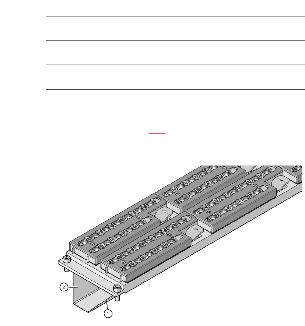
Fig. 7.1 - 6 Assembly position
(1) Sloping side points towards the component trolley docking unit
(2) Vertical side points towards the PCB conveyor
Nozzle Changer for the 20 Segment Collect&Place CA Head
Dimensions (length x width x height) 449 x 94.5 x 79 mm³
Number of magazines 6 with 12 nozzle garages each
a
a) All 6 magazines have to be set up
Number of nozzle holders 72
Nozzle types 10xx, 11xx and 12xx
Nozzle changeover time approx. 2s per nozzle
Compressed air connection 0.48 MPa (4.8 bar)
User Manual SIPLACE CA 7 Station Enlargements
Edition 08/2011 EN 7.1 Nozzle Changer
431
Align the nozzle changer so that the sloping side points towards the component trolley dock-
ing unit.
WARNING 7
Only install the associated nozzle changer for each placement head. There is a risk of head
crashes with mixed configurations.
Only use reject bins marked [03003719-06] at locations without SWS. At locations with SWS
only use reject bins marked [03070917-01]. Otherwise there is a risk of collision with the com-
ponent sensor of the C&P20 placement head (see section 2.6.9, page 76).
7.1.2.5 Functional Description
The nozzles are located in nozzle garages and are fixed by a movable locking plate. A pneumatic
cylinder moves the locking plate by 7 mm. Depending on the position of the locking plate, all noz-
zles are either clamped into place or released. The default position of the locking plate, i.e. if there
is no nozzle change in progress, is "closed".
Each magazine on the nozzle changer has two positioning fiducials for detecting the position and
orientation of the magazine. The magazine locations are numbered from 1-6 for the nozzle
changers of "row 1" and from 7-12 for the "row 2" nozzle changers (see fig. 7.1 - 4
). The 12 nozzle
garages in the magazines are also numbered consecutively (see fig. 7.1 - 9
). 7
NOTE 7
Special magazines can be made after consulting with ASM Assembly Systems GmbH & Co.KGa
and receive a seperate marking.
Nozzle Pick Up 7
– The Z-axis of the Collect&Place CA head moves downwards.
– The locking plate (item 2 in fig. 7.1 - 7
) opens and releases the nozzles.
– The nozzle is taken up by the sleeve of the Collect&Place CA head.
– The Z axis moves up.

7 Station Enlargements User Manual SIPLACE CA
7.1 Nozzle Changer Edition 08/2011 EN
432
Placing a Nozzle Down 7
– The locking plate (item 2 in fig. 7.1 - 7) opens and releases the nozzles.
– The Z-axis of the Collect&Place CA head moves downwards and places the nozzle down.
– The locking plate closes.
– The Z-axis of the Collect&Place CA head moves upwards.
Rejecting Defective Nozzles 7
– At the reject unit (item 4 in fig. 7.1 - 4) the Z-axis of the Collect&Place CA head moves down-
wards and transfers the defective nozzle to the reject unit. The nozzle is turned and does not
fit through the opening any longer.
– The Z axis moves up again and the nozzle is stripped from the sleeve opening.
– The nozzle drops into the reject bin.