00195941-03-UM SiplaceCA-EN.pdf - 第448页
7 Station Enlargements User Manual SIPLACE CA 7.1 Nozzle Changer Edition 08/2011 EN 448 7.1.4 Nozzle Changer for the 6 Segment Collect&Place CA Head [001 19662-xx]Nozzle changer HF/X/CA/ D3, 6 segment Collect&Pla…
User Manual SIPLACE CA 7 Station Enlargements
Edition 08/2011 EN 7.1 Nozzle Changer
447
7.1.3.9 Nozzle Changer "Row 2" for the 12 Segment Collect&Place CA Head
[00119663-xx] Nozzle changer 2 HF/X/CA/D3, 12 segment Collect&Place head
The "row 2" nozzle changer may be installed at the following locations:
CA4 machine: locations 1, 2, 3 and 4 (see fig. 7.1 - 12
, page 439)
CA3 machine: Locations 1, , 3 and 4 (see fig. 7.1 - 13
, page 440)
The retrofit package contains the nozzle changer and an assembly kit.
7
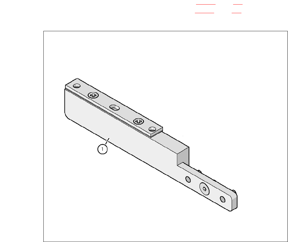
Fig. 7.1 - 18 Assembly kit for the nozzle changer "Row 2"
(1) Assembly kit for the nozzle changer "Row 2"
7 Station Enlargements User Manual SIPLACE CA
7.1 Nozzle Changer Edition 08/2011 EN
448
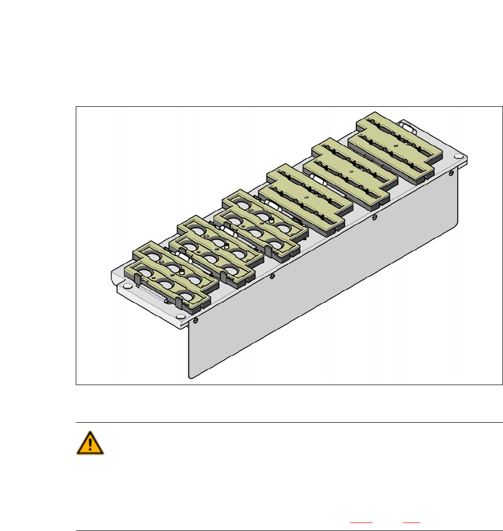
7.1.4 Nozzle Changer for the 6 Segment Collect&Place CA Head
[00119662-xx]Nozzle changer HF/X/CA/D3, 6 segment Collect&Place head
This nozzle changer can hold up to 6 magazines, each with 6 nozzle holders. There are 2 maga-
zines available: magazines for nozzles of type 8xx and magazines for nozzles of type 9xx. The
magazines are seated on a common support. They are centered using two parallel pins and fixed
in place with clips.
7
Fig. 7.1 - 19 Nozzle changer for the 6 segment Collect&Place CA head
WARNING 7
Only install the associated nozzle changer for each placement head. There is a risk of head
crashes with mixed configurations.
Only use reject bins marked [03003719-06]. Otherwise there is a risk of collision with the com-
ponent sensor of the C&P20 placement head (see section 2.6.9, page 76).
User Manual SIPLACE CA 7 Station Enlargements
Edition 08/2011 EN 7.1 Nozzle Changer
449
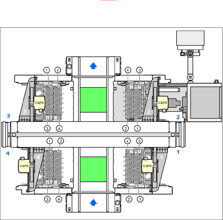
7.1.4.1 Position of Nozzle Changer for C&P6CA Head in CA4 Machines
Locations 1, 2, 3 and 4 can accommodate up to 2 nozzle changers each for the 6 segment
Collect& Place CA head (item 1 and 2 in fig. 7.1 - 20
). This gives a total capacity of 8 nozzle chang-
ers with 48 magazines and a total of 288 nozzle holders.
7
Fig. 7.1 - 20 Position of nozzle changer for C&P6 head in CA4 machines
(1) Nozzle changer, "row 1"
(2) Nozzle changer, "row 2"
(3) Reject bin for components
(4) Take-off device and reject bin for nozzles
(5) Nozzle magazine