00195941-03-UM SiplaceCA-EN.pdf - 第206页
3 Technical Data User Manual SIPLACE CA 3.8 Placement Heads Edition 08/2011 EN 206 The sequence s of movements of the rotation an d translation axes are co ntrolled b y control cir- cuits. Position and speed sensors se n…

User Manual SIPLACE CA 3 Technical Data
Edition 08/2011 EN 3.8 Placement Heads
205
3.8.6.1 Description
This highly developed placement head consits of two placement heads of the same design cou-
pled to one another (Twin head), which operate by the Pick&Place principle. The TwinHead is suit-
able for processing particularly difficult or large components. Two components are picked up by
the placement head, optically centered on the way to the placement position and rotated into the
necessary placement angle. They are then placed gently and accurately onto the PCB with a con-
trolled blast of air.
New nozzles (type 5xx) have been developed for the TwinHead. With the help of an adapter, you
can also use nozzles from the Pick&Place head, of type 4xx and nozzles from the Collect&Place
CA heads, of type 8xx and 9xx.
Control and Self-Learning Functions 3
The TwinHead's reliability can be further increased with various checking and self-learning func-
tions.
– For example, vacuum checks at the nozzles indicate whether the component was picked up
or set down correctly.
– A force sensor measures and monitors the specified component placement forces.
– High-resolution, intelligent vision modules, such as the fine-pitch and flip-chip vision modules,
identify and correct minute deviations from the desired component position, thus guarantee-
ing a correct placement position. The component cameras are permanently fixed to the ma-
chine frame.
– The component package form is also checked, and the component is not placed if the geo-
metric data thus determined differs from the programmed data.
– In the event of compressed air or power failure, the vertical axis (Z-axis) is lifted to a safe po-
sition, to prevent a head crash.
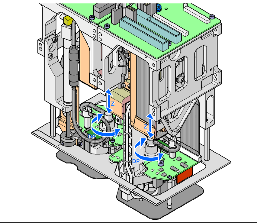
3.8.6.2 Functional Description
The TwinHead consists of two Pick&Place heads that are coupled to one another, but are con-
trolled independently. Each head has two axes, the Z-axis and the DP axis (see fig. 3.8 - 11
).
The travel range of the Z-axis is recorded with a high-resolution linear incremental measuring sys-
tem. The Z axis performs a vertical movement. A linear motor raises and lowers the Z axis, and
components are picked up from feeder modules or trays and lowered onto the PCB. The Z axis is
an "intelligent axis". It "notes" the pickup height for feeder modules and trays and the placement
height for each component. This can speed up the placement process. The programmed place-
ment force is measured and monitored by a force sensor.
The DP axis rotates the optically centered component to the desired placement angle. The rota-
tion axis is driven by a stepping motor. The motor shaft is designed as a sleeve. At the top end is
the incremental disk for angle analysis, while the nozzle holding device is at the bottom end.
3 Technical Data User Manual SIPLACE CA
3.8 Placement Heads Edition 08/2011 EN
206
The sequences of movements of the rotation and translation axes are controlled by control cir-
cuits. Position and speed sensors send the actual values for the axis movement to the axis control.
The nominal and actual values are compared and used to determine the force and speed param-
eters for the servo amplifier, and thus the axis movement to be performed.
The vacuum values at the nozzle are constantly checked throughout the entire pickup and place-
ment process in order to keep the placement error rate as low as possible.
3
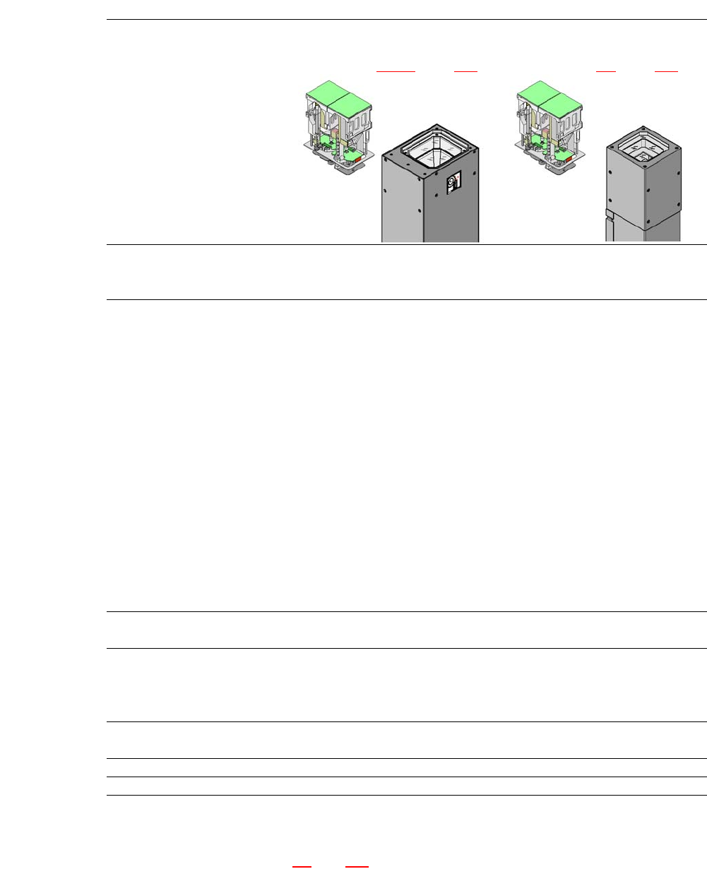
Fig. 3.8 - 13 Functional Description
User Manual SIPLACE CA 3 Technical Data
Edition 08/2011 EN 3.8 Placement Heads
207
3.8.6.3 Technical Data
Optical centering with
Restriction:
The SWS cannot be combined
with a TwinHead.
Stationary P&P component camera
(type 33) 55 x 45, digital
(see Section 3.13.5, page 229)
Stationary P&P component camera
(type 25) 16 x 16, digital
(see Section 7.4, page 463)
Range of components
a
a) Please note that the component range that can be placed is also affected by the pad geometry, the customer-spe-
cific standards and the packaging tolerances.
0402 to SO, PLCC, QFP, BGA, spe-
cial component, bare die, flip chip
0201 to SO, PLCC, QFP, sockets,
plugs, BGA, special components,
bare dies, flip-chips, shields
Component specifications
Maximum height
Min. lead pitch
Min. lead width
Min. ball pitch
min. ball diameter
Min. dimensions
Maximum dimensions
Max. weight
25 mm (higher heights on request)
0.3 mm
0.15 mm
0.35 mm
0.2 mm
1,0 mm x 0,5 mm
55 45 mm (simple measurement)
For use with two nozzles
50 mm x 50 mm or
69 mm x 10 mm
When operating with a nozzle:
85 mm x 85 mm or
125 mm x 10 mm
Max. 200 mm x 125 mm (with
restrictions)
100 g
b
b) If standard nozzles are used
25 mm (higher heights on request)
0.25 mm
0.1 mm
0.14 mm
0.08 mm
1,0 mm x 0,5 mm
16 mm (simple measurement)
100 g
b
Programmable set-down force 1.0 N - 15 N
2.0 N - 30 N
c
c) SIPLACE high-force head, section 7.3, page 462.
1.0 N - 15 N
2.0 N - 30 N
c
Nozzle types 5 xx (standard)
4 xx + adapter
8 xx + adapter
9 xx + adapter
5 xx (standard)
4 xx + adapter
8 xx + adapter
9 xx + adapter
Nozzle distance of the two
Pick&Place heads
70.8 mm 70.8 mm
X/Y accuracy (SMD) ± 26 µm/3, ± 35 µm/4 ± 22 µm / 3 , ± 30 µm / 4
Angular accuracy ± 0.05° / 3, ± 0.07° / 4 ± 0.05° / 3, ± 0.07° / 4