00195941-03-UM SiplaceCA-EN.pdf - 第159页
User Manual SIPLACE CA 3 Technical Data Edition 08/2011 EN 3.7 SIPLACE Wafer System (SWS) 159 3 Fig. 3.7 - 1 1 Positions flip head/ Die attach segment The transfer position of the flip head, the pick up and discharge pos…
3 Technical Data User Manual SIPLACE CA
3.7 SIPLACE Wafer System (SWS) Edition 08/2011 EN
158
3
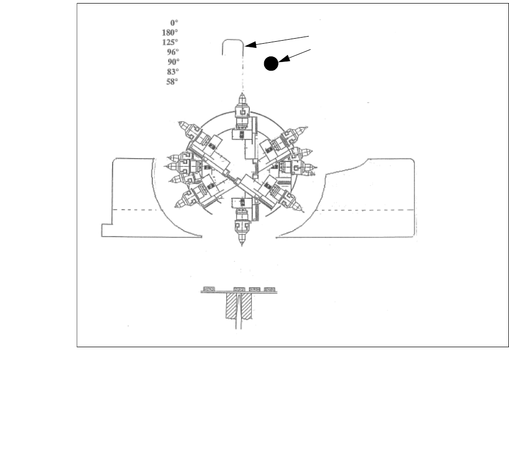
Fig. 3.7 - 10 Initialization of the flip roations axis
(1) Mechanical Stop
(2) Home sensor
The home sensor is used to initialize the flip rotation axis. During the initialization the rotation axis
travels slowly to discharge of the home sensor. Afterwards the first zero puls is looked up in an
aerea of 0-30° of the rotation axis. Through that the zero position of the flip rotation axis is defined.
Reject bin
Segment no. 2
Reject bin
Segment no. 1
1. Mechanical Stop
2. Home sensor
User Manual SIPLACE CA 3 Technical Data
Edition 08/2011 EN 3.7 SIPLACE Wafer System (SWS)
159
3
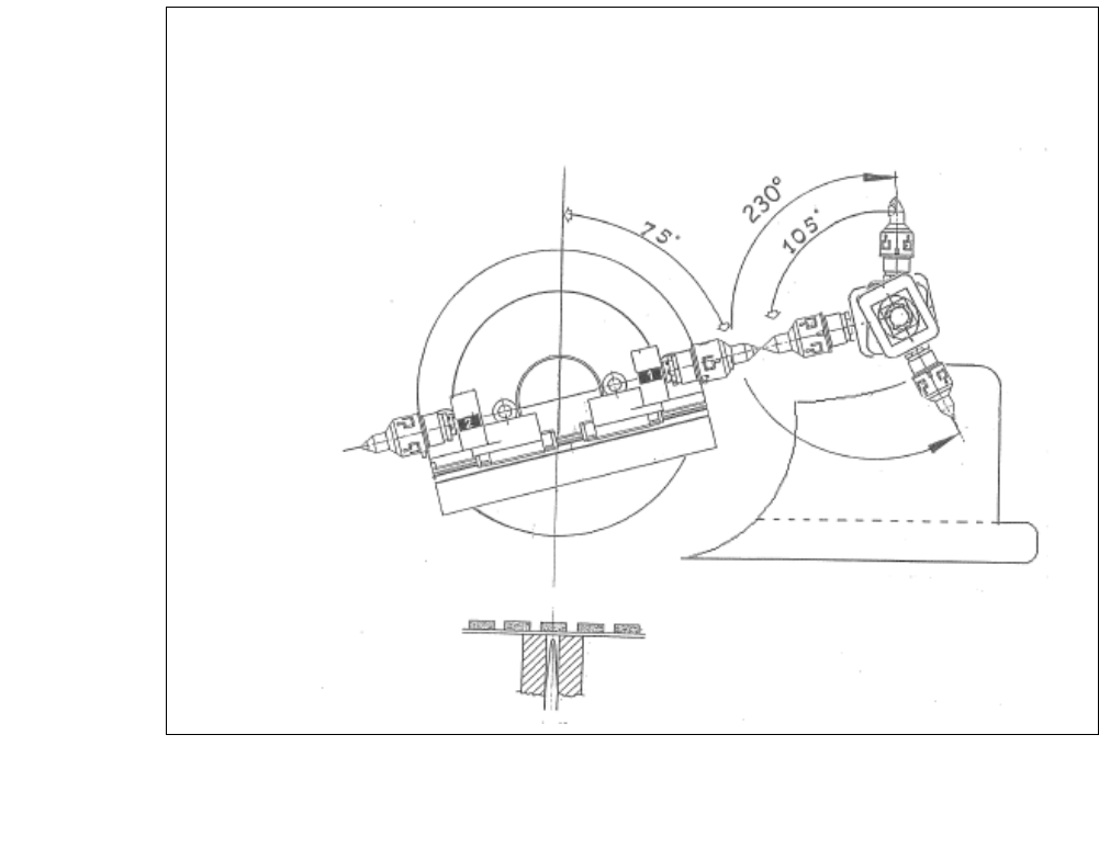
Fig. 3.7 - 11 Positions flip head/ Die attach segment
The transfer position of the flip head, the pick up and discharge position, as well as the transfer
position of the die attach segment to the placement head.
3 Technical Data User Manual SIPLACE CA
3.7 SIPLACE Wafer System (SWS) Edition 08/2011 EN
160
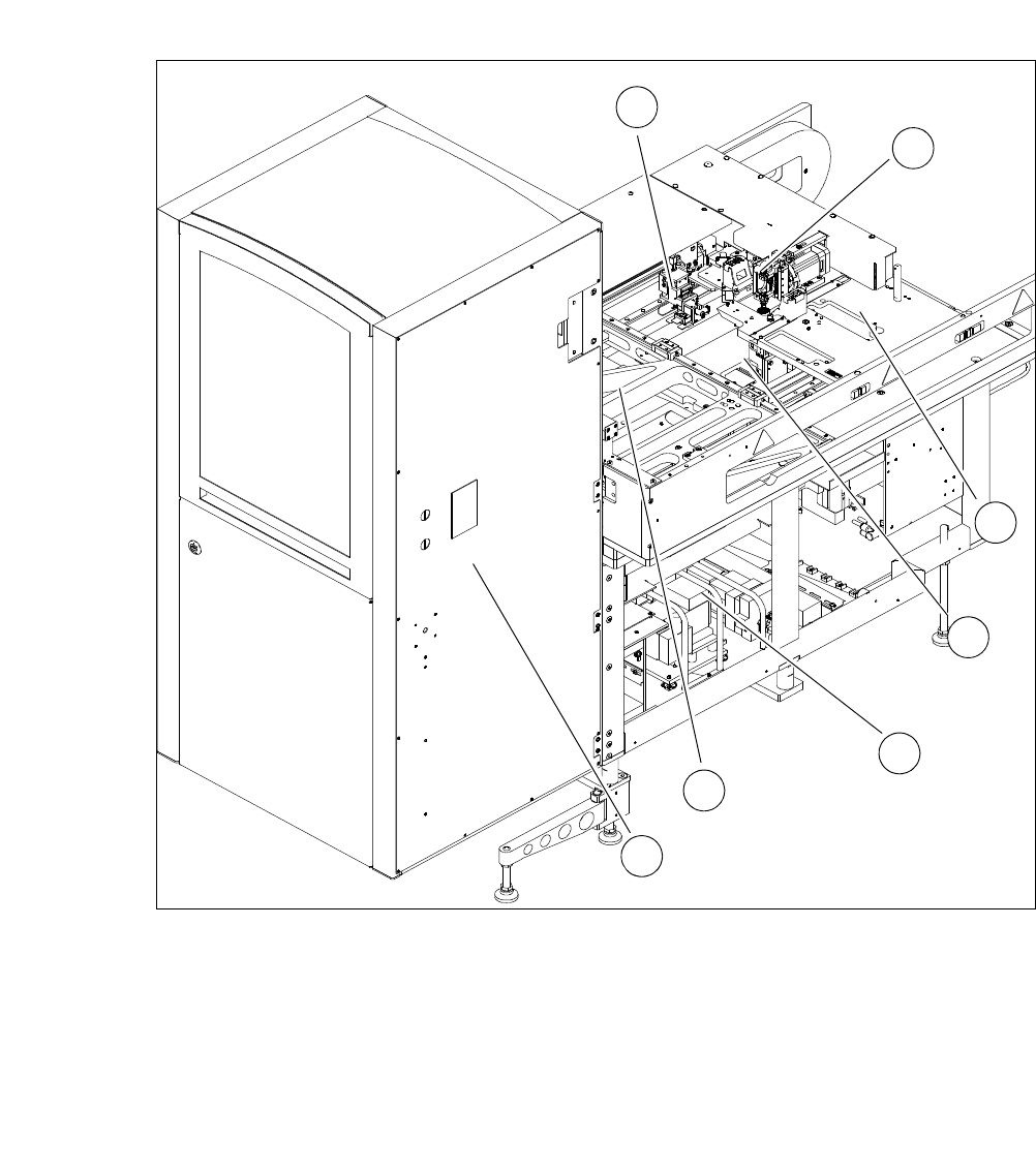
3.7.5 Overview of Modules
Fig. 3.7 - 12 Overview of the SWS
3
(1) Gripper (2) Flip unit
(3) Installation location for options (die attach
unit or linear dipping unit)
(4) Die ejector
(5) Supply unit (6) XY unit
(7) Magazine lift
1
2
3
4
5
6
7