00195941-03-UM SiplaceCA-EN.pdf - 第158页
3 Technical Data User Manual SIPLACE CA 3.7 SIPLACE Wafer System (SWS) Edition 08/2011 EN 158 3 Fig. 3.7 - 10 Initialization of the flip roations axis (1) Mechanical S top (2) Home senso r The home sensor is used to init…
User Manual SIPLACE CA 3 Technical Data
Edition 08/2011 EN 3.7 SIPLACE Wafer System (SWS)
157
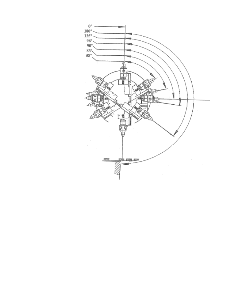
3.7.4.4 Flip Chip Coded Positions (after Calibration)
3
3
Fig. 3.7 - 9 Flip Chip Coded Positions (after calibration)
0°
Home sensor position
180°
Transfer position, segment 1
125°
Camera "free" position
96°
Discharge position, segment 1
90°
Home offset position
83°
Discharge position, segment 2
58°
Camera "free" position
3 Technical Data User Manual SIPLACE CA
3.7 SIPLACE Wafer System (SWS) Edition 08/2011 EN
158
3
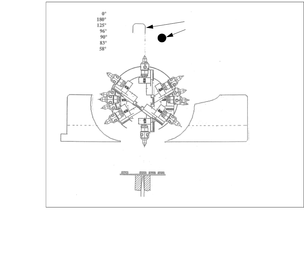
Fig. 3.7 - 10 Initialization of the flip roations axis
(1) Mechanical Stop
(2) Home sensor
The home sensor is used to initialize the flip rotation axis. During the initialization the rotation axis
travels slowly to discharge of the home sensor. Afterwards the first zero puls is looked up in an
aerea of 0-30° of the rotation axis. Through that the zero position of the flip rotation axis is defined.
Reject bin
Segment no. 2
Reject bin
Segment no. 1
1. Mechanical Stop
2. Home sensor
User Manual SIPLACE CA 3 Technical Data
Edition 08/2011 EN 3.7 SIPLACE Wafer System (SWS)
159
3
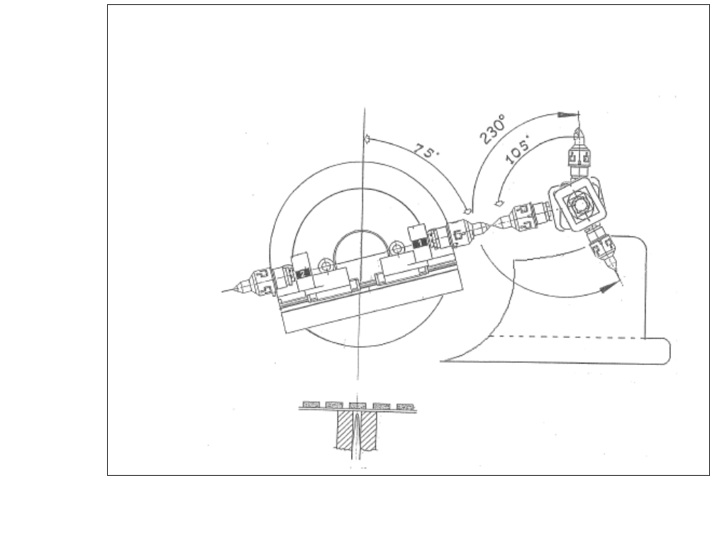
Fig. 3.7 - 11 Positions flip head/ Die attach segment
The transfer position of the flip head, the pick up and discharge position, as well as the transfer
position of the die attach segment to the placement head.