00195941-03-UM SiplaceCA-EN.pdf - 第259页
User Manual SIPLACE CA 4 Setting Up and Commissioning Edition 08/2011 EN 4.4 Infrastructure of Installation Location 259 4.4.1.2 Vib ration Thresholds The placement machine is not susceptible to fl oor vib rations but th…

4 Setting Up and Commissioning User Manual SIPLACE CA
4.4 Infrastructure of Installation Location Edition 08/2011 EN
258
4.4 Infrastructure of Installation Location
4.4.1 Recommendation for Foundation Quality
The foundation on which the placement machine or SWS is installed should be firm and level, as
dynamic forces can cause vibrations when the placement machine is operated. The size of the
vibrations depends on the construction of the foundation. The following are suitable provided that
the floor loading parameters, etc., are not exceeded:
– Reinforced concrete ceiling constructions, e.g. ceilings in production halls
– Reinforced concrete floor slabs, e.g. concrete floors in production halls without a basement
– Rooms with double floors, provided that a stable foundation is included in the space between
them. The same setup conditions apply to this intermediate foundation, which can be made
from steel girders or concrete.
4.4.1.1 Machine Weight and Floor Loading
The machine weights and floor loading values can be found in section 3.4.5, page 137.
4

User Manual SIPLACE CA 4 Setting Up and Commissioning
Edition 08/2011 EN 4.4 Infrastructure of Installation Location
259
4.4.1.2 Vibration Thresholds
The placement machine is not susceptible to floor vibrations but the following vibration limits
should still be observed.
4
4
4.4.2 Compressed Air Supply
4.4.2.1 Checking the Compressed Air Supply
Check whether the compressed air supply complies with the prescribed machine specifications
(see table in section 3.3
, page 125).
Note: 4
The document "Network Configuration (Electricity and Compressed Air) for SMD Systems at the
Customer Site" [00191409-xx] describes measures for achieving the required specifications.
Record the compressed air characteristics at the installation location.
Parameter Values
Third-octave spectral value of the vibration speed 5 - 100 Hz
v < 250 µm/s
v
max
value on the time curve
v
max
< 1.5 mm/s
4 Setting Up and Commissioning User Manual SIPLACE CA
4.4 Infrastructure of Installation Location Edition 08/2011 EN
260
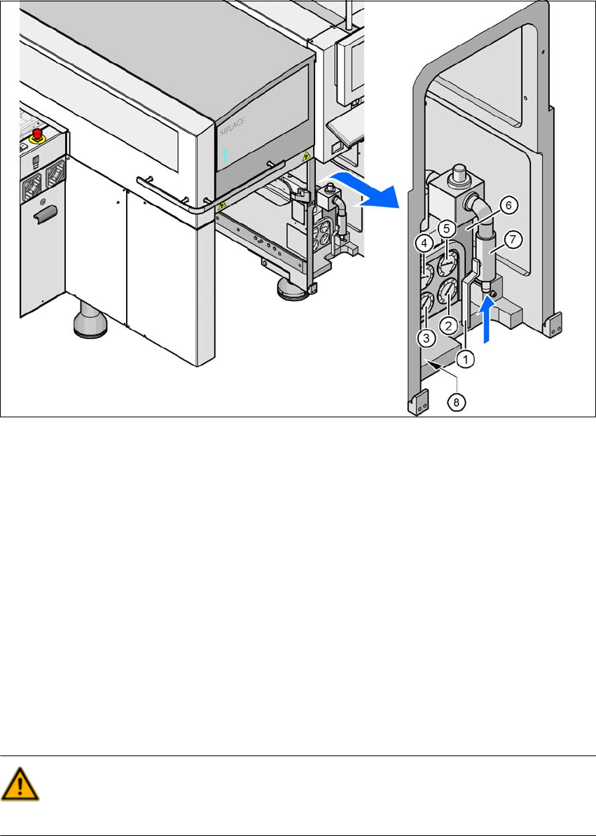
4.4.2.2 Compressed Air Connection on the Placement Machine
4
Fig. 4.4 - 1 Compressed air line connection
(1) Stop valve in the "OPEN" position
(2) Manometer for the machine component supply pressure
Target pressure: 0.5 ± 0.025 MPa, 5 ± 0.25 bar (display range 0 - 0.6 MPa, 0 - 6 bar)
(3) Manometer for the gantry distributor supply pressure
Target pressure: 0.46 ± 0.01 MPa, 4.6 ± 0.1 bar (display range 0 - 0.6 MPa, 0 - 6 bar)
(4) Manometer for the bulkcase feeder supply pressure
Target pressure: 0.25 ± 0.05 MPa, 2.5 ± 0.5 bar (display range: 0 - 0.6 MPa, 0 - 6 bar)
(5) Manometer for input pressure
Target pressure: 0.5 - 1.0 MPa, 5 - 10 bar (display range: 0 - 1.0 MPa, 0 - 10 bar)
(6) Compressed air filter
(7) Compressed air connection
(8) Hexagon socket-head screw for fixing the pneumatic unit
WARNING
NEVER detach compressed air lines while they are still pressurized. Risk of injury. 4