00195941-03-UM SiplaceCA-EN.pdf - 第478页
7 Station Enlargements User Manual SIPLACE CA 7.12 High-Resolution CO Camera for the 12 Segment C&P Head, Type 29 Edition 08/2011 EN 478 7.12 High-Resolution CO Camera for the 12 Segment C&P Head, T ype 29 [001 1…

User Manual SIPLACE CA 7 Station Enlargements
Edition 08/2011 EN 7.11 Component Sensor for the C&P12 Head
477
NOTE 7
If you are placing 0201 components with the 906 nozzle, it is essential to use the component sen-
sor since no vacuum measurements are possible. 7
Using the component sensor can improve the dpm rate even when placing other small compo-
nents, such as 0402 or 0603 components. When you select a component sensor from the pack-
age form list, remember that the component can only be placed on machines that are equipped
with that component sensor.
If you wish to test components with the component sensor, then it must be configured on the line.
The following alternatives are then available:
New set-up The setup optimization automatically assigns the components to the
component sensor, if the sensor is installed.
Old set-up A new GF number is assigned to components to be checked with the
component sensor.
Central data management If not every machine on the line is equipped with the component sen-
sor, then a new package form number is assigned for every compo-
nent to be checked with the component sensor.
NOTE 7
– Only service technicians of the ASM Assembly Systems GmbH & Co.KG may retrofit the PCB
sensor.
– Use the SITEST program to recalibrate the 12 segment C&P head after installing the compo-
nent sensor.
7 Station Enlargements User Manual SIPLACE CA
7.12 High-Resolution CO Camera for the 12 Segment C&P Head, Type 29 Edition 08/2011 EN
478
7.12 High-Resolution CO Camera for the 12 Segment C&P Head, Type 29
[00119779] High resolution camera, C&P12, digital
7.12.1 Structure
7
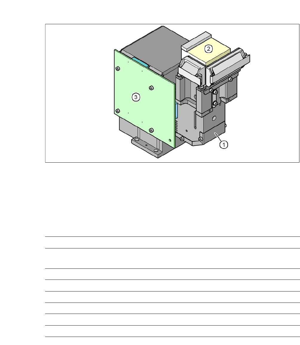
Fig. 7.12 - 1 C&P component camera, type 29, 27 x 27, digital
(1) Component camera lens and illumination
(2) Camera amplifier
(3) Illumination control
7.12.2 Technical Data
7
Component dimensions 0,3 mm x 0,3 mm to 18,7 mm x 18,7 mm
Range of components 0201
a
18,7 mm 18,7 mm to flip chip, bare die, PLCC44, BGA, µBGA,
TSOP, QFP, SO to SO32, DRAM
Min. lead pitch 0.3 mm
Min. lead width 0.15 mm
Min. ball pitch 0.25 mm
Min. ball diameter 0.14 mm
Field of vision 32 mm x 32 mm
Illumination method Front-illumination (5 levels, programable as required)
a) With 0201 package
User Manual SIPLACE CA 7 Station Enlargements
Edition 08/2011 EN 7.13 Coplanarity Laser Module
479
7.13 Coplanarity Laser Module
[00119719-xx] Coplanarity module SIPLACE X-/CA-/D-series
7.13.1 Functional Description
The coplanarity laser module is used to measure vertical bending of the leads. The lead length is
measured without contact using the laser triangulation principle.
7
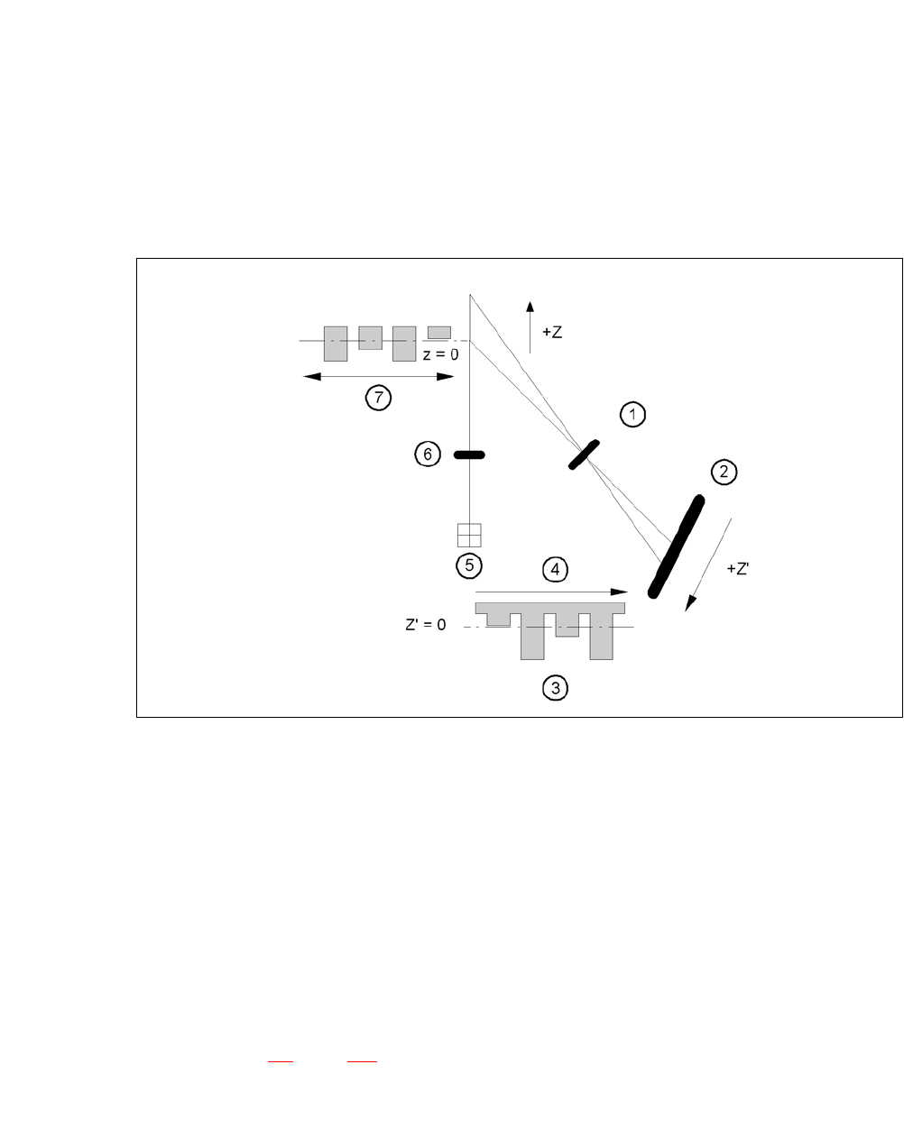
Fig. 7.13 - 1 Laser triangulation measurement principle
(1) Receiver lens
(2) Detector
(3) Measuring signal
(4) Time t
(5) Laser
(6) Transmitter lens
(7) Travel direction
7
The TwinHead picks up the component to be checked, enters it optically with the component cam-
era (see section 7.4
, page 463) and moves in succession all four sides over the fixed laser beam
of the coplanarity laser module. In this way, every lead is scanned from below by the laser beam.
The laser light scattered by the underside of the lead is recorded by a sensor, and is then used to
calculate the exact position of the lead with respect to the PCB.