00195941-03-UM SiplaceCA-EN.pdf - 第211页
User Manual SIPLACE CA 3 Technical Data Edition 08/2011 EN 3.10 Controls on the Placement Machine 211 3.10 Controls on the Placement Machine 3.10.1 Controls and Displays 3 Fig. 3.10 - 1 Controls and displays (1) Operator…
3 Technical Data User Manual SIPLACE CA
3.9 Electrical and Pneumatic Connection Points Edition 08/2011 EN
210
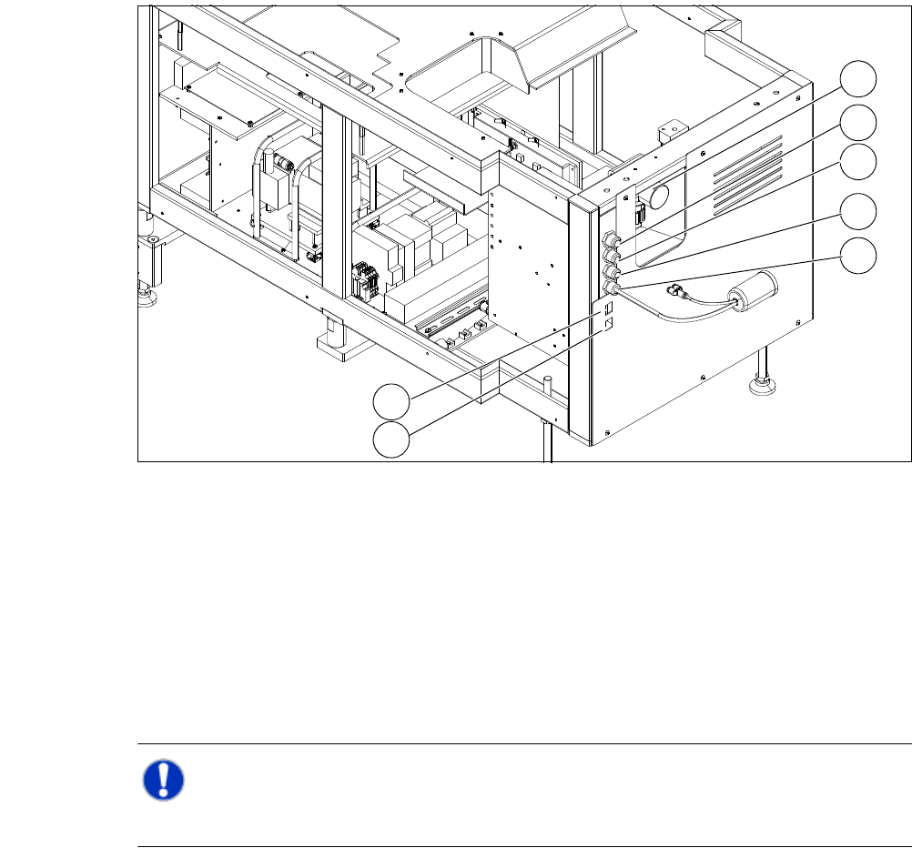
3.9.3 Electrical and Pneumatical Connection Point at the SWS
3
Fig. 3.9 - 3 Electrical and pneumatical connection point at the SWS
3
NOTE 3
The connection points of the SWS can be easily accessed when the unit is not installed.
(1) Manometer for compressed air supply (2) Voltage supply
(3) Communication with SIPLACE machine (4) CAN bus
(5) Compressed air connection (modified
adapter dummy connector [03011592-01])
(6) LAN1
(7) LAN2
2
1
3
4
5
6
7
User Manual SIPLACE CA 3 Technical Data
Edition 08/2011 EN 3.10 Controls on the Placement Machine
211
3.10 Controls on the Placement Machine
3.10.1 Controls and Displays
3
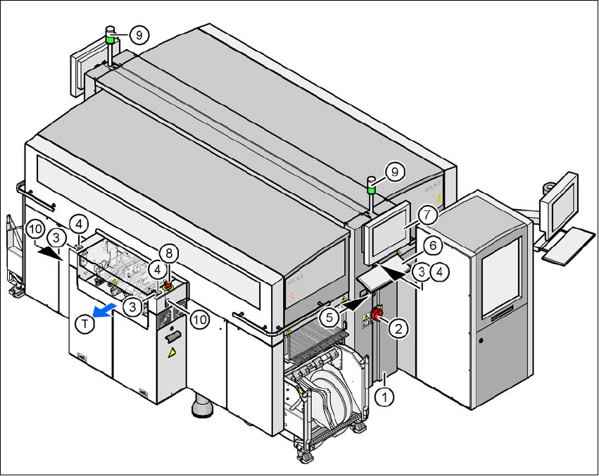
Fig. 3.10 - 1 Controls and displays
(1) Operator panel on the power supply side (7) LCD touchscreen
(2) Main switch (8) EMERGENCY STOP button
(3) Stop button (black) (9) Indicator lamps
(4) Start button (white) (10)Button for docking and undocking the
component trolley
(5) Component counter
(6) Keyboard (T) Direction of PCB transport

3 Technical Data User Manual SIPLACE CA
3.10 Controls on the Placement Machine Edition 08/2011 EN
212
3.10.2 Description
All the controls can be reached by a 1.40 m tall person.
Main switch 3
The main switch is used for switching the power supply to the placement machine on and off.
WARNING
Some parts inside the placement machine will still carry potentially lethal voltages, even when the
machine is switched off at the main switch. 3
Stop button 3
This button stops placement operations at the placement machine.
Start button 3
This button starts the placement machine after it has been switched on or after malfunctions have
been fixed.
EMERGENCY STOP button 3
The EMERGENCY STOP button latches in the ON position when pressed. The power supply to
the gantry axes, the component trolleys, conveyors and used tape cutters is interrupted and the
voltage supplied to the star axes of the placement heads is reduced. Turn the button to release it.
Component counter 3
The component counter displays the number of components processed in increments of ten.
LCD touchscreen 3
Each side of the placement machine features a flat screen monitor with LCD technology and
touchscreen function.
Keyboard 3
The keyboard is located beneath the monitor.
Indicator lamps 3
The sequence of colors of the indicator lamps is white - green. They indicate the operating states
and malfunctions of the placement machine.