00195941-03-UM SiplaceCA-EN.pdf - 第241页
User Manual SIPLACE CA 3 Technical Data Edition 08/2011 EN 3.15 Flexible D ual PCB Conveyor 241 3.15.6 Definition of th e Conveyor T rack Wid th 3.15.6.1 St andard Wid th The standar d width of the conveyor track is the …
3 Technical Data User Manual SIPLACE CA
3.15 Flexible Dual PCB Conveyor Edition 08/2011 EN
240
3.15.3 Functional Description
The flexible dual conveyor has two conveyor tracks that are electrically and mechanically inde-
pendent of one another. This conveyor has the same function as the single conveyor (see section
3.14.3
, page 235.
3.15.4 "Flexible Dual Conveyor" Performance Feature
The "flexible dual conveyor" performance feature allows the conveyor track to be widened beyond
the standard width of 216 mm. Over-wide PCBs can then be processed in a machine with a dual
conveyor. The conveyor sides of the second conveyor track are moved fully together, which de-
activates the conveyor track at the same time.
3
Fig. 3.15 - 2 Flexible dual conveyor in Single conveyor mode
3
3
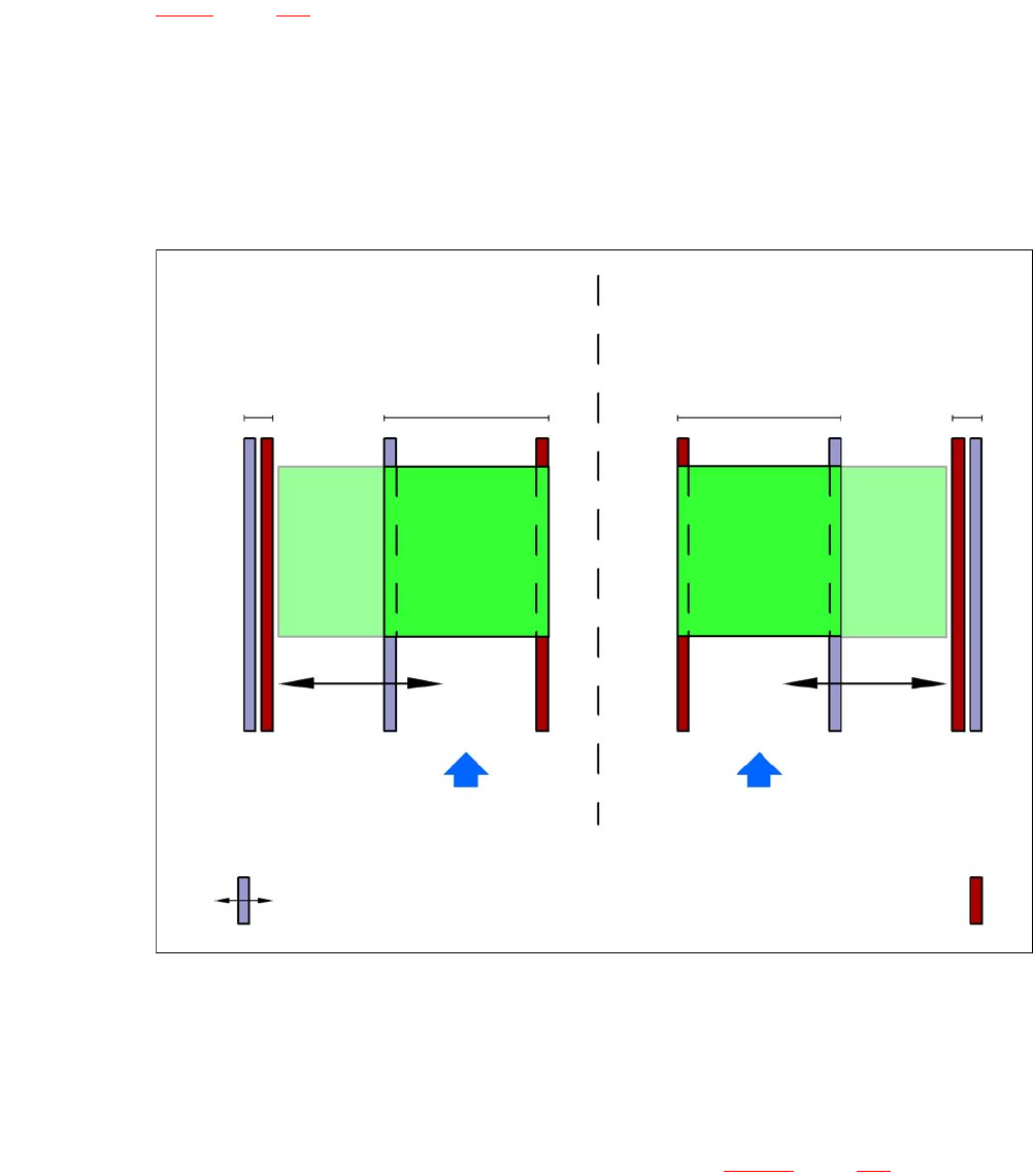
3.15.5 Definition of Conveyor Lanes
The right-hand conveyor lane (viewed from direction of transport) is known as "conveyor 1", while
the left-hand conveyor lane is known as "conveyor 2" (see fig. 3.15 - 3
, page 241).
Dual conveyor with widened conveyor track 2
(stationary conveyor side on left)
Conveyor track 2
deactivated
Conveyor track 1 Conveyor track 2 Conveyor track 1
deactivated
PCB transport direction PCB transport direction
Stationary conveyor side
Dual conveyor with widened conveyor track 1
(stationary conveyor side on right)
Movable conveyor side
User Manual SIPLACE CA 3 Technical Data
Edition 08/2011 EN 3.15 Flexible Dual PCB Conveyor
241
3.15.6 Definition of the Conveyor Track Width
3.15.6.1 Standard Width
The standard width of the conveyor track is the maximum conveyor width defined by the desired
position of the stationary conveyor side. It is no more than 216 mm per track.
3.15.6.2 Overwide Conveyor Track
The conveyor track can be widened to 250 mm maximum by moving the stationary conveyor side
out of its normal position.
3.15.6.3 Dual Conveyor in Single Conveyor Mode
The dual conveyor can be configured online to create a single conveyor. In this case, one con-
veyor lane is moved together and disabled (see fig. 3.15 - 2
, page 240). This gives a conveyor
track width of up to 450 mm.
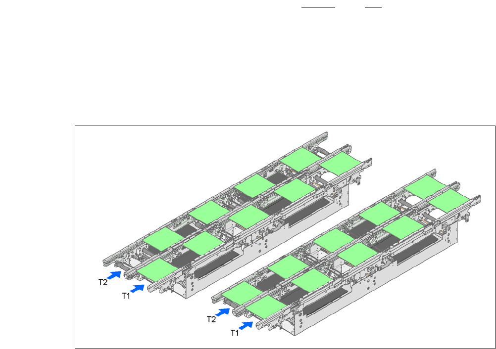
3.15.7 Ways of Transport
The flexible dual conveyor can be used in two modes:
– Synchronous transport
– Asynchronous transport
3
Fig. 3.15 - 3 Ways of transport
Synchronous transportAsynchronous transport
3 Technical Data User Manual SIPLACE CA
3.15 Flexible Dual PCB Conveyor Edition 08/2011 EN
242
3.15.7.1 Asynchronous Transport
Description 3
In asynchronous mode, only one PCB in a transport track is processed. At the same time, another
PCB in the second transport track is moved into the placement position. This saves the full con-
veying time of one PCB, thus considerably increasing performance, particularly for PCBs with a
short cycle time.
Function 3
Once the machine has received the job data (panel, setup), the PCBs on the feeding belts are con-
tinuously transported to the available processing belt (provided that the processing belt is free)
throughout the placement operation. The placement sequence starts as soon as a PCB has
moved onto the processing belt. The PCBs are processed one after another.
If the placement sequence is interrupted, the conveyor interface will be disabled and the PCBs
currently on the processing belts will be completed.
The conveyor interface is disabled or enabled simultaneously for both transport tracks.
3
3
3.15.7.2 Synchronous Transport
Description 3
In synchronous mode, two PCBs of the same size are moved into the placement position at the
same time. They must be processed as a common panel.
This facilitates the processing of a board upper and underside in one line. The time needed for
board transport is reduced as two boards are always transported at the same time. It also ensures
better utilization of the nozzle configuration.
Function 3
PCBs on conveyor tracks 1 and 2 are moved synchronously onto the conveyor sections (i.e. the
conveyors are controlled synchronously, but independently of one another). The components to
be placed on conveyor tracks 1 and 2 must be organized into a panel via two subpanels. (See the
SIPLACE Pro user manual).
If only one conveyor track (or center conveyor) is full when the placement sequence starts, the
subpanel on this section will be identified as “not for placement”.
Restrictions 3
If the dual conveyor is operated in synchronous mode, the ‘PCB whispering down the line’ option
is deactivated. PCB barcode operation is not supported in this mode. The "Global bad fiducial"
option cannot be used.