00195941-03-UM SiplaceCA-EN.pdf - 第400页
6 Component and Die Handling User Manual SIPLACE CA 6.1 X Feeder Modules for the Component Trolley from the SIPLACE X Series Edition 0 8/2011 EN 400 6 Fig. 6.1 - 18 Inserting a waffle-pack tray holder fo r the component …
User Manual SIPLACE CA 6 Component and Die Handling
Edition 08/2011 EN 6.1 X Feeder Modules for the Component Trolley from the SIPLACE X Series
399
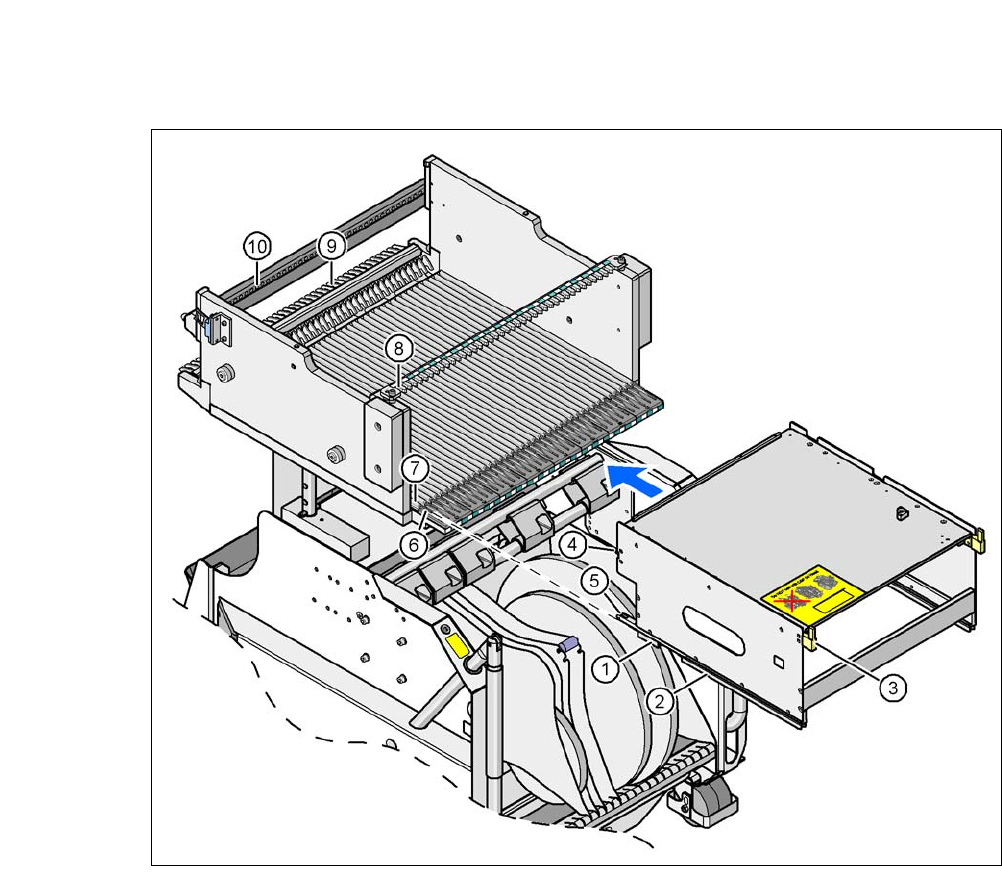
6.1.5.3 Fitting the Waffle Pack Tray Holder in X Series Component Trolleys
Position both front guiding slides (item 1 in fig. 6.1 - 18, page 400) onto the holder of the in-
sertion aid (item 6) .
Push the holder forward along the guide profiles (item 7). The holder will slide with its front
(item 1) and rear slider guides (item 2) on the guide profiles.
Carefully push the holder further until the two "front" centering pins (item 4) disappear into the
centering holes (item 10).
Watch the two "back" centering pins (item 3) on the holder. They must slide easily into the
recesses (item 8) on the centering bar.
When the holder is at the stop position, the locking tabs (item 9) engage on the locking rollers
(item 5) on the holder.
6
The waffle-pack tray holder can be locked and released via the user interface. It is therefore pos-
sible to change the holder while placement is in progress.
WARNING 6
Observe the safety instructions for assignment of locations in section 2.8.5, page 97.
6 Component and Die Handling User Manual SIPLACE CA
6.1 X Feeder Modules for the Component Trolley from the SIPLACE X Series Edition 08/2011 EN
400
6
Fig. 6.1 - 18 Inserting a waffle-pack tray holder for the component trolley from the SIPLACE X-series
(1) Front slider guide (6) Insertion aid
(2) Back slider guide (7) Slide bar (omega profile)
(3) The back centering pin (8) Recess in the centering bar for holding the
"back" centering pin
(4) Front centering pin (9) Locking latches
(5) Locking roller (10)Centering holes at the component table for re-
ceiving the front centering pin
User Manual SIPLACE CA 6 Component and Die Handling
Edition 08/2011 EN 6.2 Component Trolley, SIPLACE X-Series
401
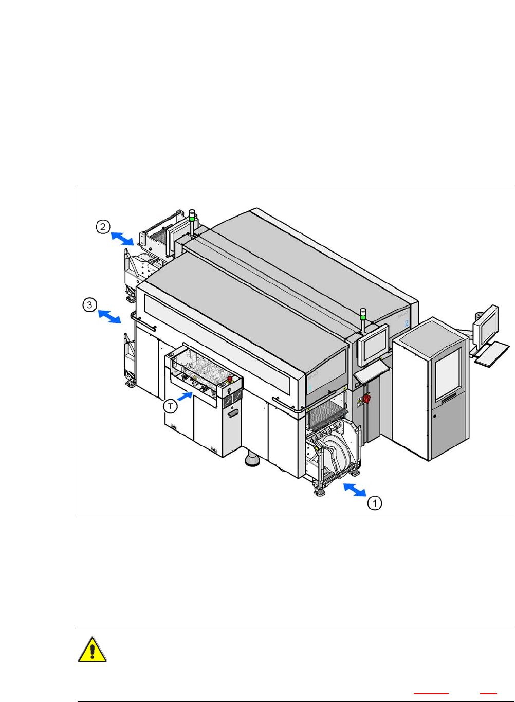
6.2 Component Trolley, SIPLACE X-Series
[00119722-xx] Component trolley for SIPLACE X series
Up to three SIPLACE X series component trolleys can be docked onto the SIPLACE CA series
machines. The locations are numbered. The following diagram shows the CA4 with an SWS at
location 2 as an example.
6
Fig. 6.2 - 1 Component trolley locations, SIPLACE X-series - example showing an SWS at location 2
(1) Location 1
(2) Location 3
(3) Location 4
(T) PCB direction of travel
CAUTION 6
The component trolleys of the SIPLACE X series may only be docked onto locations which are
equipped with the SIPLACE X series component trolley docking units (fig. 5.12 - 3, page 370).