00195941-03-UM SiplaceCA-EN.pdf - 第142页
3 Technical Data User Manual SIPLACE CA 3.4 SIPLACE CA Dimensions and Weight Edition 08/2011 EN 142 3.4.8 Center of Gravity of the CA-Series Machines 3 Fig. 3.4 - 13 Center of gravity for CA series machines with SWS 3 CA…
User Manual SIPLACE CA 3 Technical Data
Edition 08/2011 EN 3.4 SIPLACE CA Dimensions and Weight
141
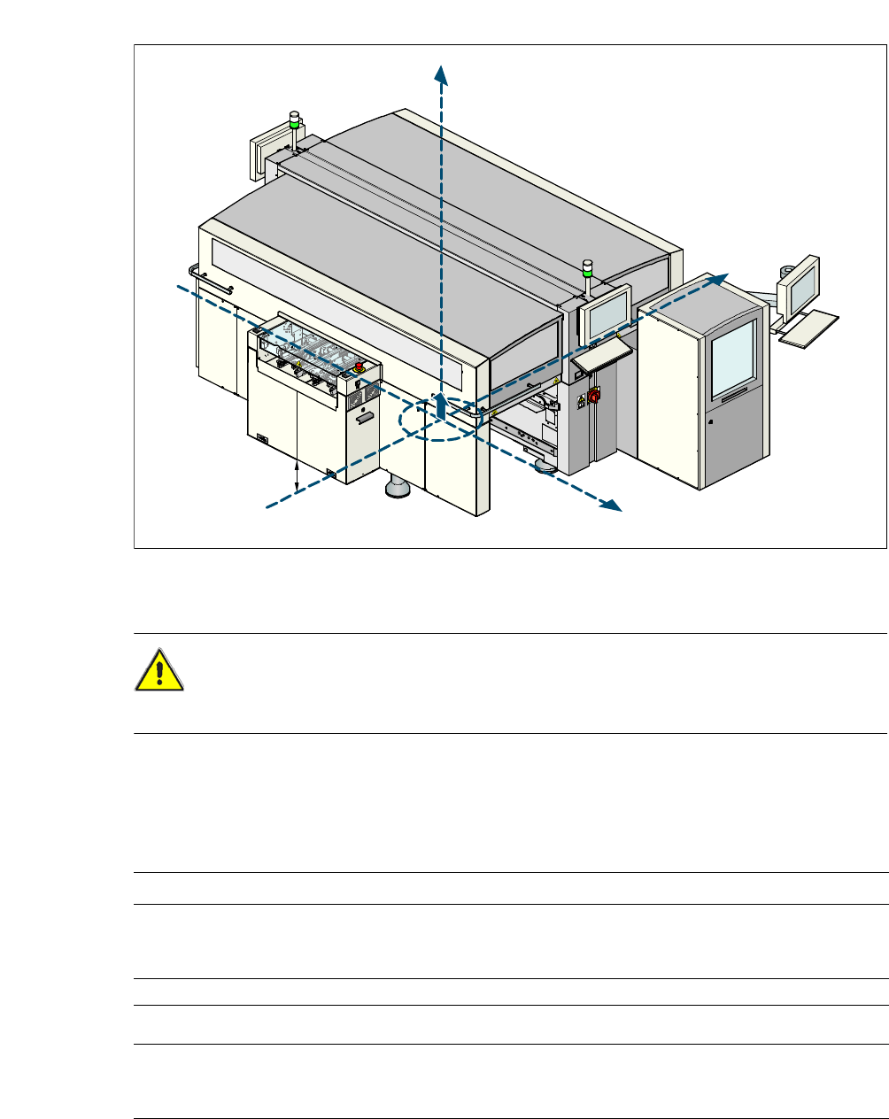
3.4.7 Maneuvering Distance for the Component Trolley of the CA3 Machine
3
3
Fig. 3.4 - 12 Maneuvering distance of the component trolley at the CA3 machine with SWS
The maneuvering distance "R" of the component trolley for the CA3 machine is:
– at the locations 1, 3 and 4
750 mm with downward folded handles respectivly
1050 mm with upward folded handles,
– on location 2
600 mm with downward folded handles respectivly
900 mm with upward folded handles.
3
3
3765
R
3410
2995
3 Technical Data User Manual SIPLACE CA
3.4 SIPLACE CA Dimensions and Weight Edition 08/2011 EN
142
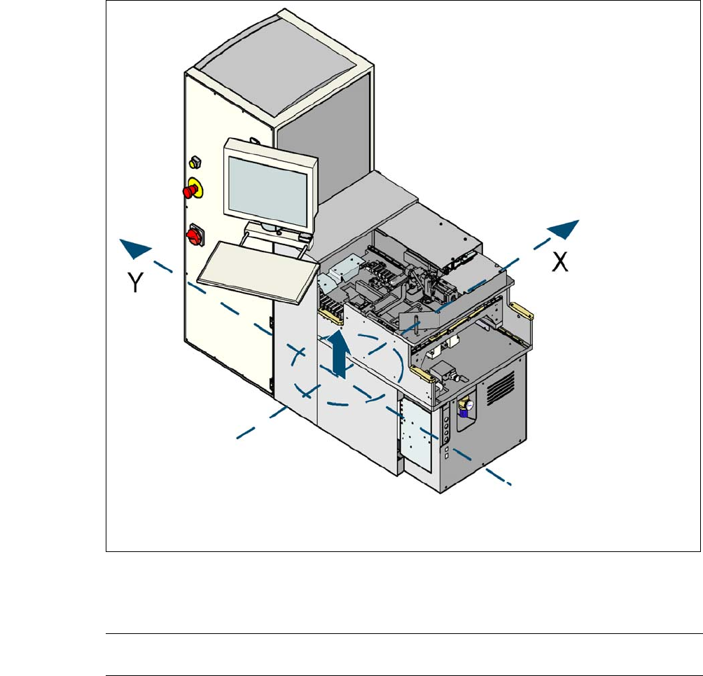
3.4.8 Center of Gravity of the CA-Series Machines
3
Fig. 3.4 - 13 Center of gravity for CA series machines with SWS
3
CAUTION 3
Before transport of the CA machine all component tables and SWS have to be removed.
Center of gravity coordinates:
These center of gravity coordinates for the placement machine apply for a PCB conveyor height
of 830 mm.
3
CA3 machine
Without SWS, without compo-
nent trolley
X coordinate 0 mm
Y coordinate 0 mm
Z coordinate 120 mm high
CA4 machine
Without SWS, without compo-
nent trolley
X coordinate 0 mm
Y coordinate 0 mm
Z coordinate 120 mm high
Y
Z
X
User Manual SIPLACE CA 3 Technical Data
Edition 08/2011 EN 3.4 SIPLACE CA Dimensions and Weight
143
3.4.9 SWS Center of Gravity
3
Fig. 3.4 - 14 Coordinate system for the SWS center of gravity
3
Center of gravity coordinates:
SWS X coordinate 0 mm
Y coordinate 655 mm