00195941-03-UM SiplaceCA-EN.pdf - 第147页
User Manual SIPLACE CA 3 Technical Data Edition 08/2011 EN 3.6 Overview of Modules 147 3.6.2 Overview of Modu les in SIPLACE CA3 3 Fig. 3.6 - 2 CA3 machine with SWS - overview o f modules (1) Machine frame (2) PCB convey…
3 Technical Data User Manual SIPLACE CA
3.6 Overview of Modules Edition 08/2011 EN
146
3.6 Overview of Modules
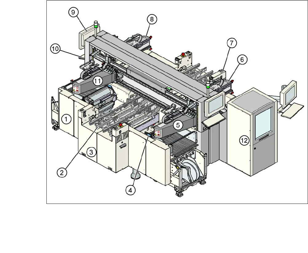
3.6.1 Overview of Modules in SIPLACE CA4
3
3
Fig. 3.6 - 1 CA4 machine with SWS - overview of modules
(1) Machine frame (2) PCB conveyor
(flexible dual conveyor)
(3) Extension kit on the PCB input side (4) Component trolley docking unit,
tape cutter, used tape channel
(5) Gantry 1 with placement head (6) Gantry 2 with placement head
(7) Extension kit on the PCB output side (8) Gantry 3 with placement head
(9) Monitor screen (2x) (10) Keyboard (2x)
(11) Gantry 4 with placement head (12)SIPLACE Wafer System (SWS) at location
2
User Manual SIPLACE CA 3 Technical Data
Edition 08/2011 EN 3.6 Overview of Modules
147
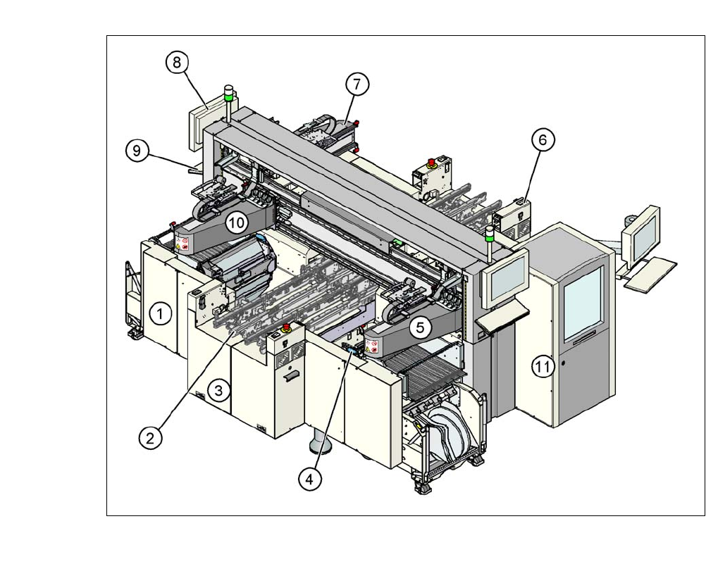
3.6.2 Overview of Modules in SIPLACE CA3
3
Fig. 3.6 - 2 CA3 machine with SWS - overview of modules
(1) Machine frame (2) PCB conveyor
(flexible dual conveyor)
(3) Extension kit on the PCB input side (4) Component trolley docking unit,
tape cutter, used tape channel
(5) Gantry 1 with placement head (6) Extension kit on the PCB output side
(7) Gantry 3 with placement head (8) Monitor screen (2x)
(9) Keyboard (2x) (10)Gantry 4 with placement head
(11) SIPLACE Wafer System (SWS) at location
2
3 Technical Data User Manual SIPLACE CA
3.7 SIPLACE Wafer System (SWS) Edition 08/2011 EN
148
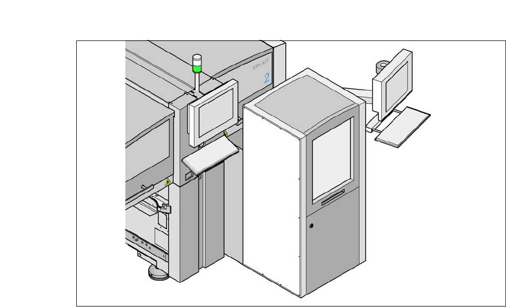
3.7 SIPLACE Wafer System (SWS)
3
Fig. 3.7 - 1 SWS at location 2 of SIPLACE CA4