00195941-03-UM SiplaceCA-EN.pdf - 第365页
User Manual SIPLACE CA 5 Tasks on the Machine Edition 08/2011 EN 5.9 Avoiding Track Errors 365 5.9 A voiding T rack Errors 5.9.1 General Make sure that the areas aroun d the feeder modules are clean and that th ere are…

5 Tasks on the Machine User Manual SIPLACE CA
5.8 Changing Setups Edition 08/2011 EN
364
5.8.2 Changing Setups at the SWS
Check if the orientation of the wafer locking bar fits with the relevant wafer size (10,5" oder
10,8" bei 8" Wafern) (see fig. 3.7 - 19
, page168).
NOTE 5
During commissioning, the SWS is configured according to the required wafer size (8" or 12")
and thickness of the wafer frame. Adapting the SWS to other sizes and thicknesses is de-
scribed in the service manual.
Adjust the feeder plate for the wafer magazine (8" or 12") and insert the new magazine. Make
sure the magazine has the correct configuration.
Check the needle configuration at the die ejector (see section 5.2.5, page 338).
Check, if the flip unit is equipped with the appropriate tools and nozzles (see section 5.2.6,
page 342).
Load or compile the required product (see software guide).

User Manual SIPLACE CA 5 Tasks on the Machine
Edition 08/2011 EN 5.9 Avoiding Track Errors
365
5.9 Avoiding Track Errors
5.9.1 General
Make sure that the areas around the feeder modules are clean and that there are no loose
components in the feeder area or under the feeder modules.
Refill promptly with components.
Splice the tapes early. This generally means that you are to prepare the splicing material
when there is still approximately 1.5 m of tape on the reel.
Handle the feeder modules carefully when you insert them into or remove them from the com-
ponent feeder table as these are high-precision devices.
For X feeder modules, lower the pickup window since it can easily be damaged when raised.
NOTE 5
A raised pickup window leads to noticeably impaired pickup quality.
Please check whether the pickup position is set correctly for the feeder modules.
5
5
5
5
5 Tasks on the Machine User Manual SIPLACE CA
5.9 Avoiding Track Errors Edition 08/2011 EN
366
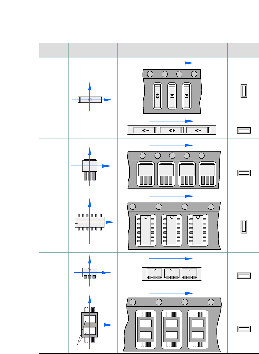
5.9.2 Component Coordinate System and Pickup Angle
5
Fig. 5.9 - 1 Position of the component and its pickup angle
Special
component
Stick
magazine:
Chip-
components
with polarity
0402
2220
The anode must be
aligned with the +X
coordinate.
Package form Coordinate system
Position in the feeder module
Pickup angle/
nozzle angle
Tape:
SOT 23
Stick
magazine:
Tape:
Tape:
SO-IC
DIL-IC
SOT 194
Tape:
Holes
Y
X
Y
X
Y
X
Y
X
Y
X
90°
90°
0°
90°
-90°
0°