00195941-03-UM SiplaceCA-EN.pdf - 第348页
5 Tasks on the Mach ine User Manual SIPLACE CA 5.4 Performing Inspections Edition 08/2011 EN 348 5.4.5 Inserting Partition Plat es into the T ape Cont ainer The partition plate has dif ferent edges and can be inserted …

User Manual SIPLACE CA 5 Tasks on the Machine
Edition 08/2011 EN 5.4 Performing Inspections
347
X-series feeder modules can process component tapes without problems if the lateral offset be-
tween the feeder module and the tape reel does not exceed 60 mm. If a predefined setup means
that the maximum permitted offset cannot be maintained, we recommend that you use the mount
for an additional tape reel (item 1). Simply insert the mount into the holder (item 2) and push it until
the offset is less than the maximum permitted value of 60 mm. The component trolley has 5 hold-
ers in total. Each tape reel mount can hold 2 tape reels, which means that up to ten 15" (381 mm)
reels can be positioned above the tape container.
5 Tasks on the Machine User Manual SIPLACE CA
5.4 Performing Inspections Edition 08/2011 EN
348
5.4.5 Inserting Partition Plates into the Tape Container
The partition plate has different edges and can be inserted into the tape container in two ways.
When using spindles, the partition plate recesses for the spindles should face upwards (see
item 4 in fig. 5.4 - 3
). If you are not using spindles, the rounded edge of the partition plate should
face upwards (see item 5 in fig.
5.4 - 3
).
Insert the partition plates as shown in fig. 5.4 - 3 and take into account that the smallest pitch
for the tape container is a 2-fold pitch. This will help avoid placement errors.
Check that the partition plates engage in the same positions on the three guide rails. Other-
wise the partition plate will be offset or bent.
5
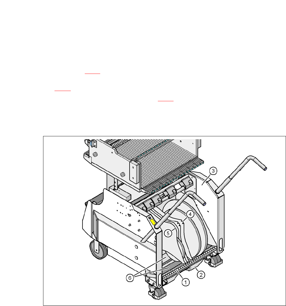
Fig. 5.4 - 3 Partition plates in the tape container
(1) Guide rail for the partition plates
(2) Waste bin for unused tape
(3) Tape container
(4) Position of the partition plate when spindles are used
(5) Position of the partition plate when no spindles are used
(6) Sliding surfaces for the tape reels
User Manual SIPLACE CA 5 Tasks on the Machine
Edition 08/2011 EN 5.4 Performing Inspections
349
5.4.6 Using Spindles for Large Tape Reels
5
5
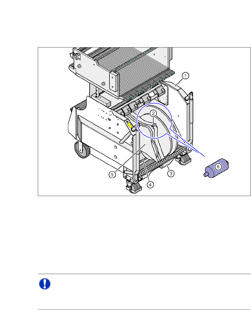
Fig. 5.4 - 4 Component trolley, SIPLACE X-series, with tape container and spindle
(1) Component trolley
(2) Position of the spindle
(3) Waste bin for unused tape
(4) Tape container
(5) Partition plate
(6) Spindle (enlarged)
Note: 5
X-series component trolleys do not generally need spindles. However, if the "Time-out" error
message occurs increasingly on the X feeder module, we recommend that you do use spindles.