00195941-03-UM SiplaceCA-EN.pdf - 第209页
User Manual SIPLACE CA 3 Technical Data Edition 08/2011 EN 3.9 Electrical and Pneumatic Connection Points 209 3.9.2 Pneumatical Connection Po int on the Placement Machine Fig. 3.9 - 2 Pneumatical connection point on the …
3 Technical Data User Manual SIPLACE CA
3.9 Electrical and Pneumatic Connection Points Edition 08/2011 EN
208
3.9 Electrical and Pneumatic Connection Points
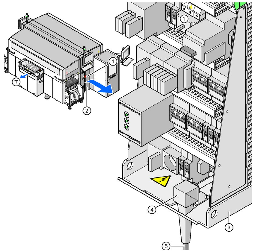
3.9.1 Electrical Connection Points (Placement Machine)
3
Fig. 3.9 - 1 Electrical connection point on the placement machine
(1) Main switch
(2) Cover above the power supply unit
(3) Power supply unit
(4) Angled cable gland
(5) Power cable
(T) Direction of PCB transport
User Manual SIPLACE CA 3 Technical Data
Edition 08/2011 EN 3.9 Electrical and Pneumatic Connection Points
209
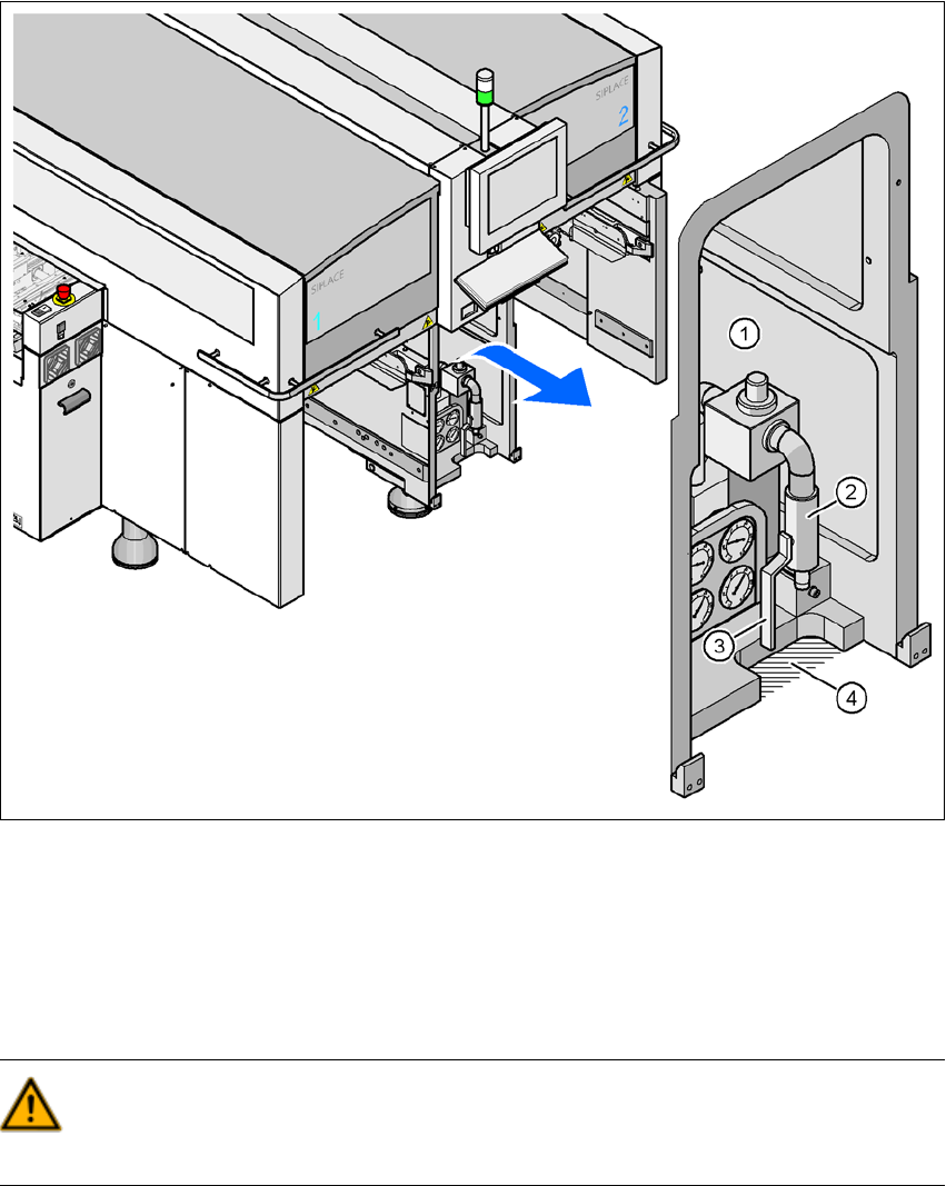
3.9.2 Pneumatical Connection Point on the Placement Machine
Fig. 3.9 - 2 Pneumatical connection point on the placement machine
(1) Pneumatic unit
(2) Connection coupling for the compressed air hose
(3) Shutoff valve
(4) Cutoff for the pneumatic hose
WARNING
NEVER detach compressed air lines while they are still pressurized. Risk of injury. 3
3 Technical Data User Manual SIPLACE CA
3.9 Electrical and Pneumatic Connection Points Edition 08/2011 EN
210
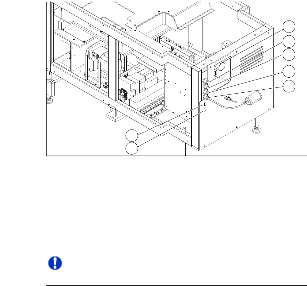
3.9.3 Electrical and Pneumatical Connection Point at the SWS
3
Fig. 3.9 - 3 Electrical and pneumatical connection point at the SWS
3
NOTE 3
The connection points of the SWS can be easily accessed when the unit is not installed.
(1) Manometer for compressed air supply (2) Voltage supply
(3) Communication with SIPLACE machine (4) CAN bus
(5) Compressed air connection (modified
adapter dummy connector [03011592-01])
(6) LAN1
(7) LAN2
2
1
3
4
5
6
7