00195941-03-UM SiplaceCA-EN.pdf - 第354页
5 Tasks on the Mach ine User Manual SIPLACE CA 5.5 Configuring Feeders Edition 08/2011 EN 354 Check the "ba ck" center ing pin (item 3) of the feeder mo dule as you do so. This must slide easily into the rece…
User Manual SIPLACE CA 5 Tasks on the Machine
Edition 08/2011 EN 5.5 Configuring Feeders
353
5.5.3.2 Using the X Feeder Module on the Component Table
5
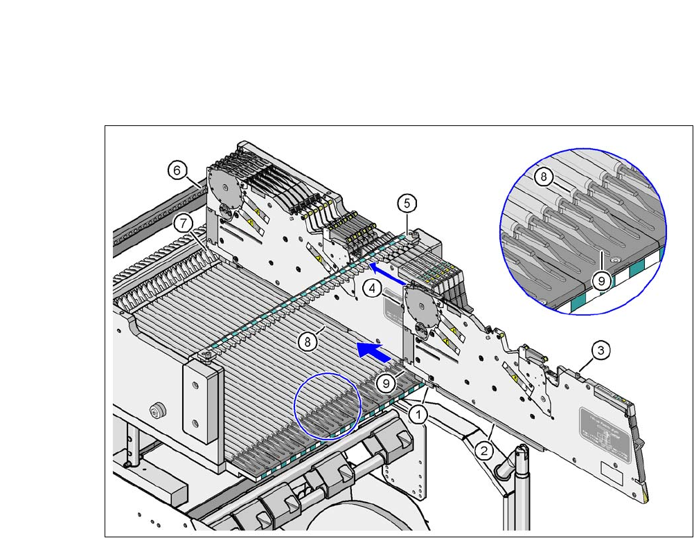
Fig. 5.5 - 3 Using the X feeder module on the component table
(1) Front slider guide for the X feeder module
(2) Back slider guide for the X feeder module
(3) "Back" centering pin on the X feeder module
(4) "Front" centering pin on the X feeder module
(5) Recesses in the centering bar for holding the "back" centering pin
(6) Centering holes at the component table for receiving the front centering pin
(7) Locking latches
(8) Guide profile for the component table ( profile)
(9) Insertion aid for the feeder module
5
Place the front slider guide (item 1) of the feeder module on the insertion aid (item 9) for the
component table.
Hold the feeder module vertically and push it forward, along the guide profile (item 8). The
front (item 1) and rear (item 2) slider guides of the feeder module slide on the guide profile
(item 8).
Carefully push the feeder module further until the "front" centering pin (item 4) is pushed into
the centering hole (item 6).
5 Tasks on the Machine User Manual SIPLACE CA
5.5 Configuring Feeders Edition 08/2011 EN
354
Check the "back" centering pin (item 3) of the feeder module as you do so. This must slide
easily into the recess (item 5) in the centering bar, otherwise the feeder module is not seated
vertically on the component table or it was not placed on the guide profile (item 8) correctly.
The locking latch (item 7) engages with the locking roller of the feeder (item 1 in fig. 6.1 - 1).
If you have forgotten to engage the removal handle (item 1 in fig. 5.5 - 2
, page 352), the status
display on the feeder operating panel will shine red after a few seconds. The LCD display will
show the error message "Handle --->>" (see fig. 5.7 - 1
, page 360). 5
Engage the removal handle (item 1 in fig. 5.5 - 2). The feeder module's status display
now lights up green and the feeder module is on standby. The track number and con-
veyor increment can be read on the LCD display once more.
5.5.4 Placing Component Tape on the X Feeder Module
5.5.4.1 Checking the X Tape Feeder
When you insert the tape into the feeder, check whether there are any components in the
pickup window area (item 2 in fig. 5.5 - 5
).
Remove any components that you find since they could cause a fault.
5.5.4.2 Preparing the Component Tape for Insertion
Check that there is a straight cut edge at the start of the component tape.
If the transport holes are torn or bent, cut off this part of the tape.
Also make sure that there are no streaks of adhesive on the cover foil.
Pull around 30 cm cover foil away from the component tape if this does not expose any
components.
NOTE 5
Use the SMD tape threading aid if there is not enough cover foil available, to prevent compo-
nents being lost:
for the 8 mm - tape: [00355265-xx]
for the 12 mm - tape: [00356342-xx]
User Manual SIPLACE CA 5 Tasks on the Machine
Edition 08/2011 EN 5.5 Configuring Feeders
355
Shorten the component tape with the now exposed component pockets by around 3 cm.
Remove the components from the open tape pockets.
Wrap the cover foil around the front edge of the tape along the bottom of the tape.
5.5.4.3 Inserting the Tape into the X Feeder
5
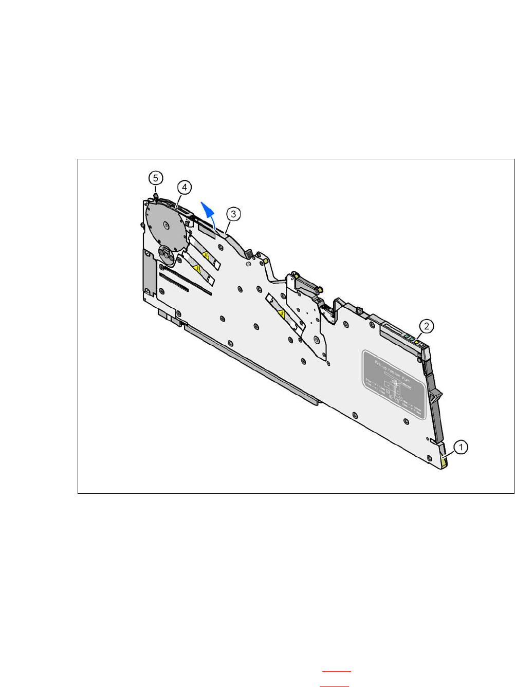
Fig. 5.5 - 4 Inserting the component tape
(1) Entry of the tape guide channel
(2) Operating panel
(3) Outlet of the tape guide channel
(4) Pickup window
(5) Lever for raising the pickup window
5
Hold the component tape so that the transport holes are on the left-hand side viewed in the
direction of travel.
Insert the tape into the inlet opening (item 1 in fig. 5.5 - 4) of the tape guide channel, until the
tape protrudes from the tape outlet (item 3 in fig. 5.5 - 4
).
Pull the component tape up and out, and fold the cover foil back against the top of the tape.