00195941-03-UM SiplaceCA-EN.pdf - 第169页
User Manual SIPLACE CA 3 Technical Data Edition 08/2011 EN 3.7 SIPLACE Wafer System (SWS) 169 Fig. 3.7 - 20 W afer support with a wafer inserted ( example for 12") (1) Recess f or the defined positioning at the pins…
3 Technical Data User Manual SIPLACE CA
3.7 SIPLACE Wafer System (SWS) Edition 08/2011 EN
168
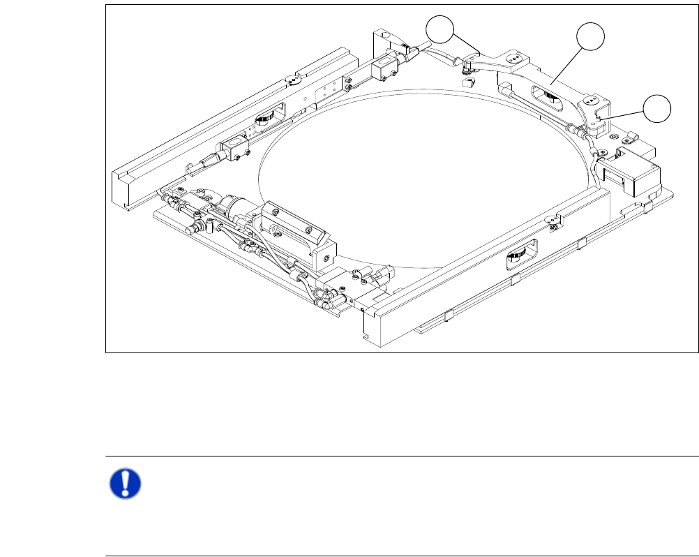
Wafer support
Thewafer support is installed on the XY-unit and so a part of the wafer table. The wafers are fixed
to this for the ejection procedure.
3
Fig. 3.7 - 19 Wafer support without a wafer inserted (example for 12")
(1) Pin for the locking and position detection of 12" wafers
(2) Wafer locking bar
NOTE 3
For processing of 8" wafers the wafer support has to be changed. Frames with 6" wafers can be
processed with appropriate adapters.
1
2
1
User Manual SIPLACE CA 3 Technical Data
Edition 08/2011 EN 3.7 SIPLACE Wafer System (SWS)
169
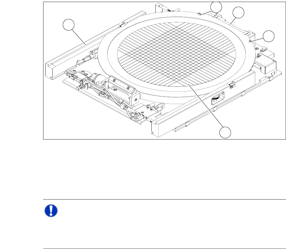
Fig. 3.7 - 20 Wafer support with a wafer inserted (example for 12")
(1) Recess for the defined positioning at the pins of the locking bar
(2) Wafer locking bar
(3) Wafer
(4) Rail
NOTE 3
In case of 8"wafer supports care must be taken to ensure, that the wafer locking bar (2) is
installed so that the pins of the locking bar fit correctly into the recess of the wafer frame. Other-
wise the frame is not properly recognised during clamping.
3
1
4
2
1
3 Technical Data User Manual SIPLACE CA
3.7 SIPLACE Wafer System (SWS) Edition 08/2011 EN
170
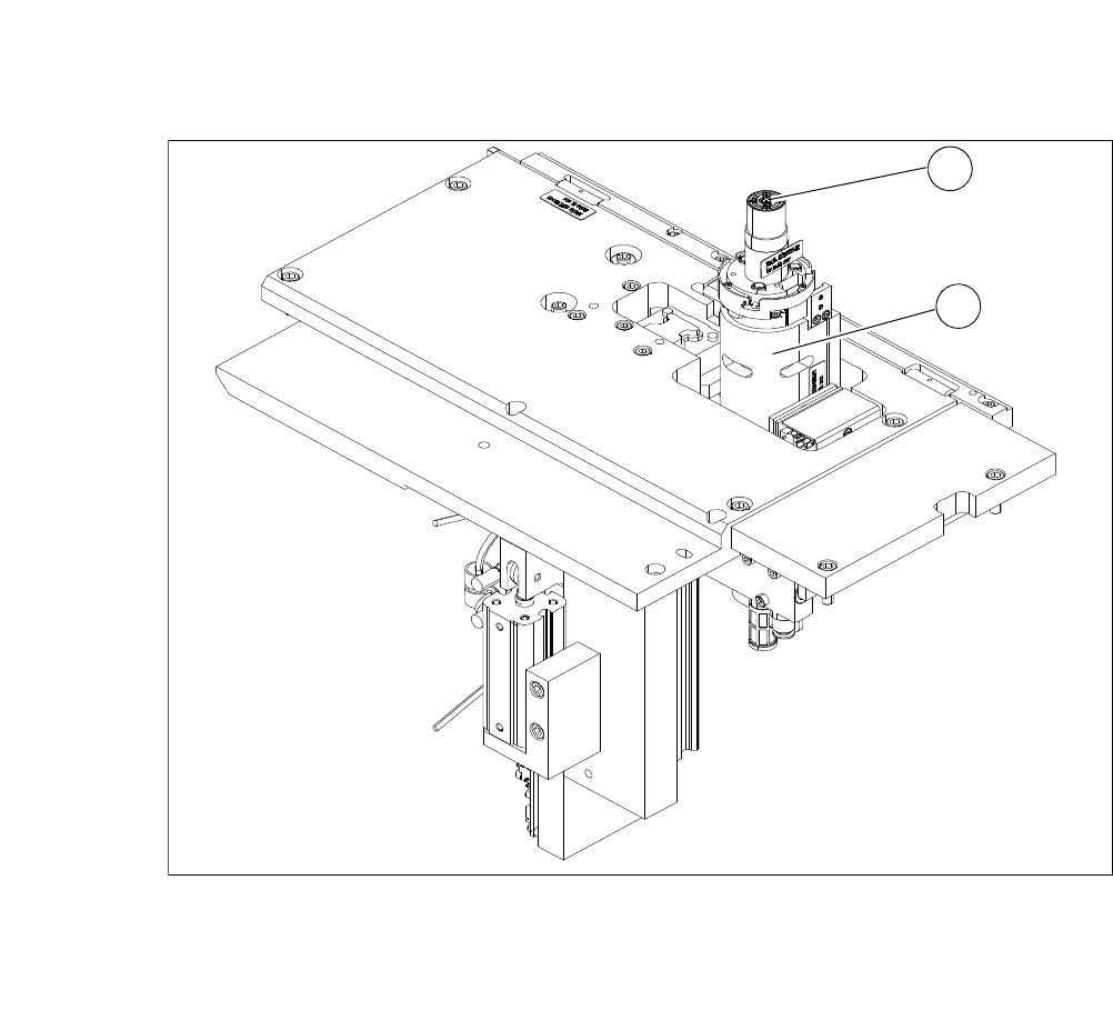
3.7.6.5 Die Ejector
According to the location (2 and 4 or 1 and 3) there are two different variants that only differ in their
mirror-inverted arrangement of the modules.
3
Fig. 3.7 - 21 Main modules of the die ejector
(1) Ejector tool
(2) Z axis
1
2