00195941-03-UM SiplaceCA-EN.pdf - 第266页
4 Setting Up and Commissioning User Manual SIPLACE CA 4.4 Infrastructure of Installation Location Edition 08/2011 EN 266 4.4.4.5 Checking the Inrush Current Limit ation Jumpers The inrush current limitation must be confi…

User Manual SIPLACE CA 4 Setting Up and Commissioning
Edition 08/2011 EN 4.4 Infrastructure of Installation Location
265
Crimp a ferrule onto each end of the wire.
Loosen the nut on the angled cable gland (item 2 in fig. 4.4 - 3).
Fold up the angled cable gland.
Run the power supply cable through the angled cable gland and to the terminal panel X100
(see X100 in fig. 4.4 - 4
).
Connect the cable to the terminal and ensure that it has a sufficient bending radius. The wires
must not be kinked.
Close the angled cable gland (item 2 in fig. 4.4 - 3) and manually tighten the nut.
4 Setting Up and Commissioning User Manual SIPLACE CA
4.4 Infrastructure of Installation Location Edition 08/2011 EN
266
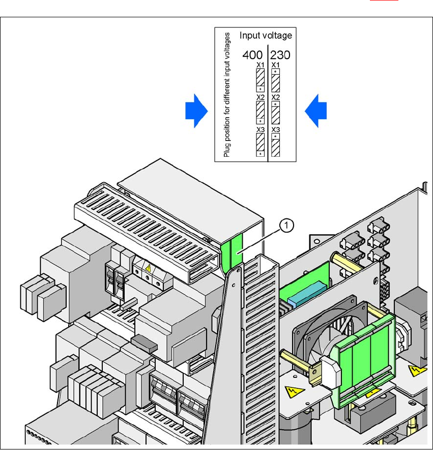
4.4.4.5 Checking the Inrush Current Limitation Jumpers
The inrush current limitation must be configured in relation to the supply voltage. This is achieved
with the help of plug-in bridges on the inrush current limitation board (item 1 in fig. 4.4 - 5
).
4
Fig. 4.4 - 5 Position of the board and connectors for the inrush current limitation
4
(1) Inrush current limitation board
X1, X2, X3 Connectors for configuring the inrush current limitation on the board
Check the jumper assignment and correct if necessary.
3 x 380 VAC
3 x 400 VAC
3 x 415 VAC
3 x 208 VAC
3 x 230 VAC

User Manual SIPLACE CA 4 Setting Up and Commissioning
Edition 08/2011 EN 4.5 Setting Up the Placement Machine
267
4.5 Setting Up the Placement Machine
4.5.1 PCB Conveyor Height for Placement Machine
The placement machine can be set to accommodate the following PCB conveyor heights:
830 mm ± 15 mm (standard height) 4
900 mm ± 15 mm 4
930 mm ± 15 mm 4
950 mm ± 15 mm (SMEMA height) 4
NOTE 4
The PCB conveyor height is the distance between the top edge of the PCB conveyor belt and the
bottom edge of the machine feet.
4.5.2 Warning Instructions
DANGER 4
Only ASM-technicians or certified persons may set up and start up the machine.
Always follow the applicable accident prevention regulations.
When fitting the machine feet, never lie down under the placement machine. All the modules
and parts can be fitted from the spaces for the component feeder tables. If you still need to
perform assembly work to the underside of the placement machine, take appropriate mea-
sures to secure the machine first. The fork-lift truck alone is not a suitable support!
Make sure that the gantries are positioned over the PCB conveyor area so that you do not
restrict your head movement during assembly, thus excluding the risk of injury.
You require two people to set the height of the placement machine:
– One person carries out the required assembly work.
– The other person monitors the stability of the lifted machine during assembly.
Wear special safety boots to protect your feet. Each machine foot weighs 6.75 kg.