00195941-03-UM SiplaceCA-EN.pdf - 第470页
7 Station Enlargements User Manual SIPLACE CA 7.6 PCB Barcode Scanner Edition 08/2011 EN 470 7 7 7 7 7 7 7 Assembly 2 mounting holes M3 x 3.5 Dimensions 55 mm x 42 mm x 22 mm (2.17 inch x 1.65 inch x 0.87 inch) Weight 12…

User Manual SIPLACE CA 7 Station Enlargements
Edition 08/2011 EN 7.6 PCB Barcode Scanner
469
7.6.3 Technical Data - Cognex DataMan
7
Code types
1D code types UPC/EAN/JAN, Codabar,
Interleaved 2 to 5, Code 39, Code 128 and Code 93
2D code types Data Matrix ECC 0, 50, 80, 100, 140, and
200 QR-Code and microQR-Code
Picture
Sensor 1/3 inch with global shutter
(resolution 752 x 480)
Picture acquisition Max. 60 fps
Lens type Adjustable lens, 3 positions with (6.2 mm;
F:5 aperture), 40 mm, 65 mm and 105 mm working
distance
I/A
Trigger Fast trigger input, manual trigger key
Trigger voltage -25 V DC to +25 V DC
Trigger current 7.7 mA at 24 VDC
3.7 mA at 12 VDC
1.33 mA at 5 VDC
Trigger delay 1 ms (max)
Discrete inputs 2 opto-isolated (one is used as trigger)
Discrete outputs 2 opto-isolated
Status LEDs 2 Status LEDs (reading LED and communication
LED)
Beeper Programmable functions
Illumination
Illumination Types Integrated bright field lighting with exposure control
Communication
Serial RS-232E
USB Supports USB 2.0 (12 Mbit/s)
Power Supply
Power consumption 500 mA at 5 VDC max. (Peak), average.: 300 mA at
5 VDC
Operating voltage 5 V DC to 24 V DC
Mechanics
Material Aluminum housing

7 Station Enlargements User Manual SIPLACE CA
7.6 PCB Barcode Scanner Edition 08/2011 EN
470
7
7
7
7
7
7
7
Assembly 2 mounting holes M3 x 3.5
Dimensions 55 mm x 42 mm x 22 mm
(2.17 inch x 1.65 inch x 0.87 inch)
Weight 125 g ( 0.28 lb)
Environmental conditions
Operating temperature 0 ºC to 40 ºC (32 ºF to 104 ºF)
Humidity (operation) 95 % (not condensing)
Storage temperature -10 ºC to 60 ºC (-14 ºF to 140 ºF)
Humidity (storage) 95 % (not condensing)
Protection class IP-65
Vibration EN61373, inc. IEC 60068-2-6,60068-2-64 6.4 and
60068-2-27
Certificates
Approvals CE, UL, FCC, CTICK, VCCI, IC
User Manual SIPLACE CA 7 Station Enlargements
Edition 08/2011 EN 7.7 PCB Alignment
471
7.7 PCB Alignment
[00119677-xx] PCB alignment for single conveyor, SIPLACE HF/X/CA/D3
[00119678-xx] PCB alignment for dual conveyor, SIPLACE HF/X/CA/D3
7.7.1 General
PCBs to be processed sometimes have a length to width ratio of 1:2 or worse. This means that
the shorter side of the PCB points in the direction of travel. During travel, such PCBs may twist
slightly and, as a result, the fiducials no longer lie within the PCB vision camera's search window.
In this case, the "PCB alignment" option ensures that these PCBs are realigned precisely at the
stopping position.
If boards with recesses are processed in the direction of transport, this can lead to different pro-
cessing positions between machines with mechanical stoppers (HS-50, S-25 HM, F5 HM) and
machines which monitor this position with a laser light barrier (X, CA, HF series, HS-60, S-27 HM).
The "PCB alignment" option ensures that the PCBs are stopped at the same position on all PCB
conveyors. The "PCB alignment" option is available for both single and dual conveyors.
7
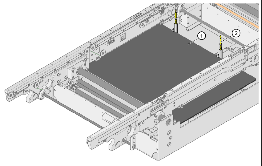
Fig. 7.7 - 1 PCB alignment
(1) Lifting table
(2) PCB stop