00195941-03-UM SiplaceCA-EN.pdf - 第345页
User Manual SIPLACE CA 5 Tasks on the Machine Edition 08/2011 EN 5.4 Performing Inspections 345 NOTE 5 Never tear the cover foil. Th is can cause problem s with the cover foil pull- of f. There is an in- tegral blade (it…
5 Tasks on the Machine User Manual SIPLACE CA
5.4 Performing Inspections Edition 08/2011 EN
344
5.4 Performing Inspections
5.4.1 Checking the Feeders (X Series)
5
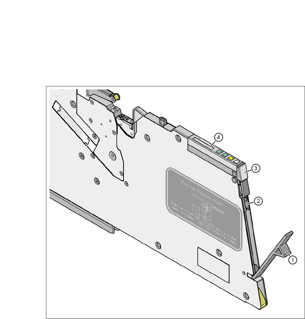
Fig. 5.4 - 1 Checking the X feeder modules
(1) Flap
(2) Blade
(3) Status display
(4) LCD display
5
Check to see whether the tape foil removal container for the X tape feeder module is full.
Open the flap (item 1). Pull out the cover foil and cut it with scissors or on the integral blade
(item 2) on 8 and 12 mm X tape feeder modules.

User Manual SIPLACE CA 5 Tasks on the Machine
Edition 08/2011 EN 5.4 Performing Inspections
345
NOTE 5
Never tear the cover foil. This can cause problems with the cover foil pull-off. There is an in-
tegral blade (item 2) for easily cutting the on the 8 and 12 mm X tape feeder modules.
Check the multicolor status display (item 3 in fig. 5.4 - 1).
– If it lights up green, the feeder module is on standby.
– If it lights up orange, it is signaling a warning. The text of the warning appears on the LCD
display (item 4 in fig. 5.4 - 1
).
– If the status display lights up red, a malfunction has occurred. The error message will ap-
pear on the LCD display (item 3 in fig. 5.4 - 1
).
For a list of the LCD and status displays on the operating panel, refer to section 5.7
, page
359
. 5
If the status display is off, the cause may be as follows: 5
– The feeder module is not in the current setup.
– The feeder module is defective.
– The feeder module has been disabled (due to a drop in pressure, for example)
5.4.2 Splicing the Belts in Time
Note:
Make sure you splice on new tapes in good time, so that the feeders do not run empty. Oth-
erwise you will experience prolonged down times.
However, do not splice the tapes too early because if you wind the end of the old tape onto
the new reel after splicing, the reel holding the new tape may become overfilled and the tape
will slip off the reel and become tangled up. This will again result in pickup errors and pro-
longed down times. 5
5 Tasks on the Machine User Manual SIPLACE CA
5.4 Performing Inspections Edition 08/2011 EN
346
5.4.3 Checking the PCB Supports
Check the position of the magnetic PCB supports on the lifting table:
– Make sure that the PCB supports do not collide with components on the underside of the
PCBs.
– In addition, make sure that the PCB supports do not collide with the PCB conveyor pan-
els.
– Use only those PCB supports described in section 7.10
, page 474.
5.4.4 Mount for additional Tape Reel (X-Series)
5
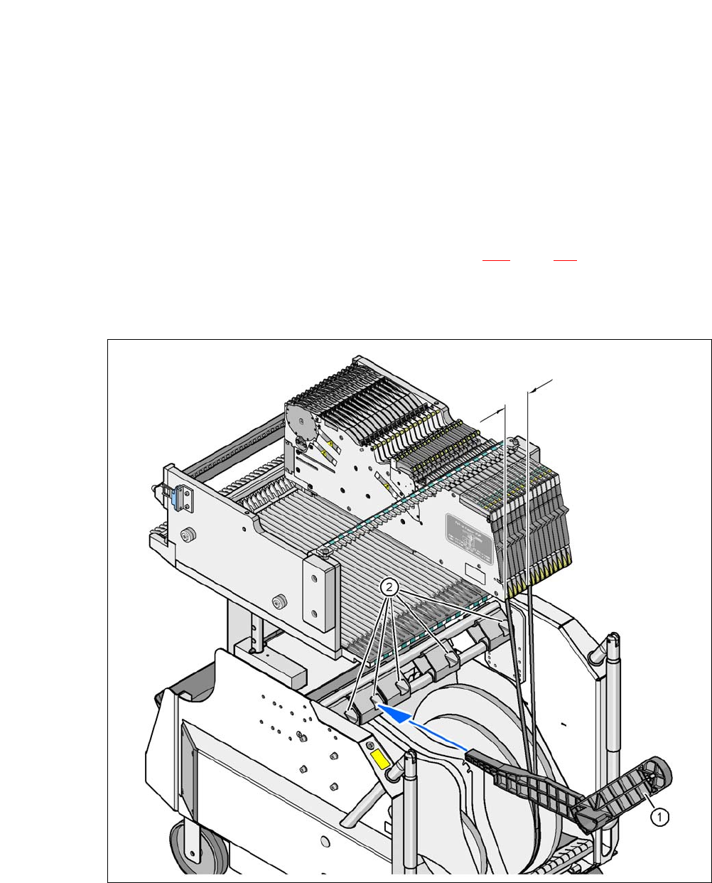
Fig. 5.4 - 2 Mount for additional Tape Reel (X-Series)
(1) Mount for additional tape reel [00141217-xx]
(2) Mounting device for the support
5
Max. 60 mm