00195941-03-UM SiplaceCA-EN.pdf - 第264页
4 Setting Up and Commissioning User Manual SIPLACE CA 4.4 Infrastructure of Installation Location Edition 08/2011 EN 264 4.4.4.4 Connecting the Power Supply Cable 4 Fig. 4.4 - 4 T e rminal panel for connecting the power …
User Manual SIPLACE CA 4 Setting Up and Commissioning
Edition 08/2011 EN 4.4 Infrastructure of Installation Location
263
WARNING 4
The electrical leads to each individual machine and to the options installed (e.g. Productivity Lift)
must be clearly labeled and easily assignable. The regulations of the country in which the
machine is operated apply.
4
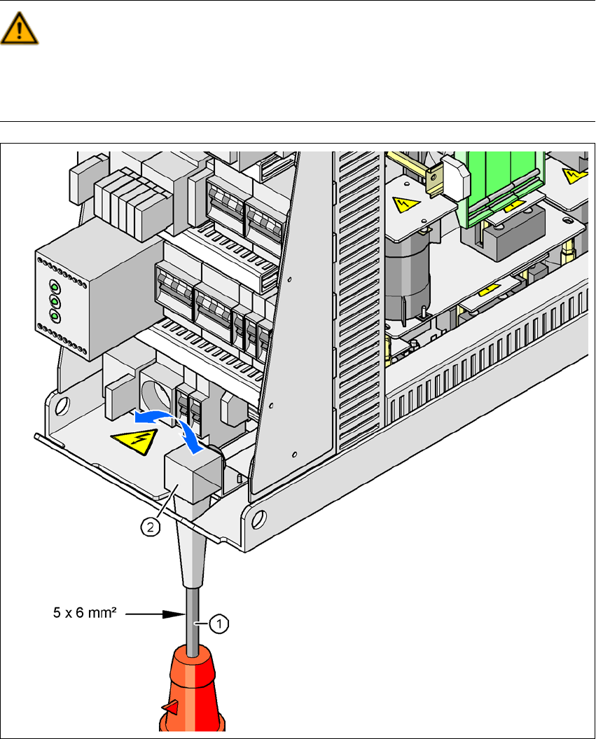
Fig. 4.4 - 3 Cross-section of the main power cable
(1) Power supply cable
(2) Angled cable gland
4 Setting Up and Commissioning User Manual SIPLACE CA
4.4 Infrastructure of Installation Location Edition 08/2011 EN
264
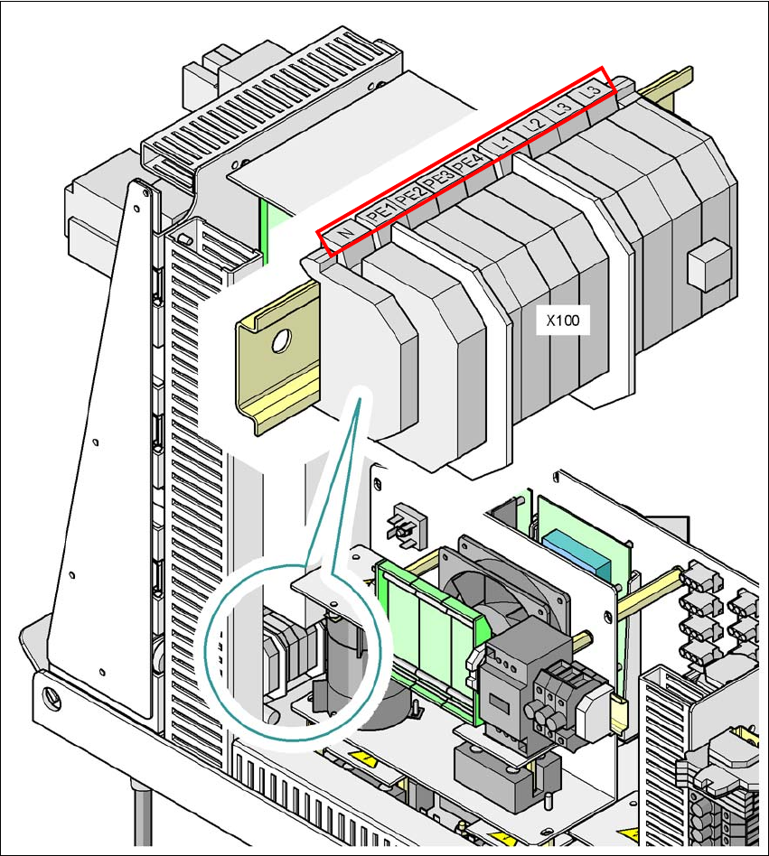
4.4.4.4 Connecting the Power Supply Cable
4
Fig. 4.4 - 4 Terminal panel for connecting the power cable
(L1) Three-phase
(L2) Three-phase
(L3) Three-phase
(N) Neutral conductor
(PE) Protective earth wires PE1, PE2, PE3, PE4
(X100) Terminal panel

User Manual SIPLACE CA 4 Setting Up and Commissioning
Edition 08/2011 EN 4.4 Infrastructure of Installation Location
265
Crimp a ferrule onto each end of the wire.
Loosen the nut on the angled cable gland (item 2 in fig. 4.4 - 3).
Fold up the angled cable gland.
Run the power supply cable through the angled cable gland and to the terminal panel X100
(see X100 in fig. 4.4 - 4
).
Connect the cable to the terminal and ensure that it has a sufficient bending radius. The wires
must not be kinked.
Close the angled cable gland (item 2 in fig. 4.4 - 3) and manually tighten the nut.