00195941-03-UM SiplaceCA-EN.pdf - 第324页
4 Setting Up and Commissioning User Manual SIPLACE CA 4.6 Installing the SWS Edition 08/2011 EN 324 Fig. 4.6 - 3 Position of the connect ions on the placement machine (1) CAN Bus connection X1x5 (2) CAN Bus connection X1…
User Manual SIPLACE CA 4 Setting Up and Commissioning
Edition 08/2011 EN 4.6 Installing the SWS
323
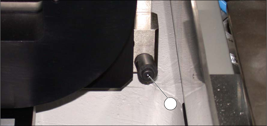
Carefully push the SWS to approx. 30 cm before the bumper (see following figure) in the
placement machine (see following figure), so that you still have enough room to connect the
SWS and placement machine connections.
Fig. 4.6 - 2 Bumper
(1) Bumper
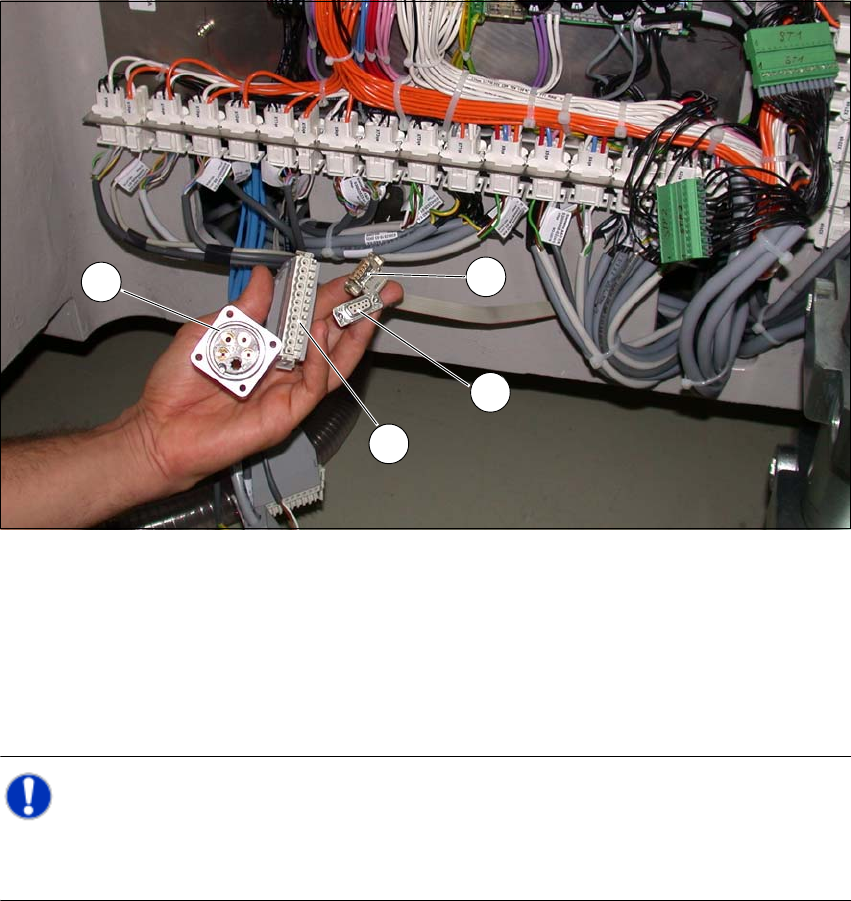
4.6.3.3 Connecting the SWS to the Placement Machine
The SWS connections need to be connected as follows to the placement machine:
– CAN Bus connections X1x6 and X1x5
– Compressed air connection to compressed air connection
– FFI communication interface W11 to FFI communication interface X1x3
1
4 Setting Up and Commissioning User Manual SIPLACE CA
4.6 Installing the SWS Edition 08/2011 EN
324
Fig. 4.6 - 3 Position of the connections on the placement machine
(1) CAN Bus connection X1x5
(2) CAN Bus connection X1x6
(3) Compressed air connection (modified dummy connector [03011592-01])
(4) FFI communication connection X1x3
Note: 4
Connect the SWS to the placement machine before performing alignment and final adjustment,
as the connection points will no longer be accessible after installation.
1
2
3
4
User Manual SIPLACE CA 4 Setting Up and Commissioning
Edition 08/2011 EN 4.6 Installing the SWS
325
4.6.3.4 Final Adjustment of the SWS
Use the fork-lift truck or hand lift to push the SWS carefully into the placement machine, as
far as the stop on the bumper.
Carefully lower the SWS with the fork-lift truck or hand lift, until it lies evenly on the contact
bars of the placement machine.
CAUTION 4
Make sure that you do not lower the hand lift too far, before fastening the screws, as the SWS
will then tip over towards the magazine lift. 4
A second person should check the stability of the SWS during lowering. 4
The following screws are needed to install the SWS:
–3x M8
–2x M6
– 4x M6 for the angle bracket (2 at the location, 2 at the wafer table)
– 1x fitting screw
Note: 4
During final installation, observe the following order of screws.
Fasten the rear clamping claw (6) loosely, with one M8 screw.
Insert the remaining screws and tighten loosely.
NOTE 4
The correct position of the SWS is ensured with the help of the fitting screw and the contact
rods in the placement machine. 4
Fasten the M6 screws (item 4 and 5) in succession, with a torque of 10 Nm.
Fasten the M8 screws (item 1, 2 and 6) in succession, with a torque of 18 Nm.
Tighten the fitting screw in item 3 with a torque of 13-14 Nm.
Tighten the angle bracket for fixing the wafer table with the M6 screws (items 7 and 8).
Fix the angle bracket with the M6 screws to the wafer table.