00195941-03-UM SiplaceCA-EN.pdf - 第222页
3 Technical Data User Manual SIPLACE CA 3.12 Gantries Edition 08/2011 EN 222 The Y axis essentially consists of the following main modules: – Y -axis linear motor (primary part) (1) – Permanent magn et (secondary p art o…
User Manual SIPLACE CA 3 Technical Data
Edition 08/2011 EN 3.12 Gantries
221
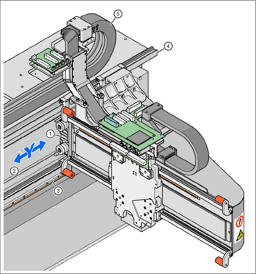
3.12.5 Structure of the Y Axis
3
Fig. 3.12 - 4 Structure of the Y axis
(1) Y-axis linear motor (primary part)
(2) Permanent magnet (secondary part of the X-axis linear motor)
(3) Linear distance measuring system
(4) Guidance system
(5) Trailing cable

3 Technical Data User Manual SIPLACE CA
3.12 Gantries Edition 08/2011 EN
222
The Y axis essentially consists of the following main modules:
– Y-axis linear motor (primary part) (1)
– Permanent magnet (secondary part of the Y-axis linear motor) (2)
– Linear distance measuring system (3)
– Guide system (4)
– Cable and hose carrier (5)
The Y axis is driven by a linear motor. The secondary part of the drive is made up of permanent
magnets and is mounted on the machine frame. The primary part is bolted to the gantry.
3.12.6 Technical Data for the Y Axis
Drive Direct, linear motor
Maximum speed 2.5 m/s
Travel range 1430 mm
Distance measuring system Metal linear scale
Length of scale 1850 mm
Resolution 1 µm

User Manual SIPLACE CA 3 Technical Data
Edition 08/2011 EN 3.13 Vision Cameras
223
3.13 Vision Cameras
Each Collect&Place CA head has an integrated component camera (see fig. 3.8 - 4 page 186, fig.
3.8 - 7
page 195 and fig. 3.8 - 10 page 200). The stationary P&P component vision camera (type
33) 55 x 45 digital for the TwinHead is permanently fixed to the machine frame.
The component vision module is used to determine:
– the precise position of the components at the nozzle and
– the geometry of the package form.
The PCB cameras are fixed to the bottom of the gantries. They use fiducials on the feeder mod-
ules to determine the exact pickup position of components, which is particularly important for
small components.
The PCB vision module uses fiducials on the PCBs to determine:
– the position of the PCB,
– its rotation angle
– and the PCB skew.
WARNING
RISK OF HEAD CRASH 3
During a placement head change from TwinHead to Collect&Place CA head, the component
camera, stationary, P&P (type 33) 55 x 45, digital, and the component camera, stationary, P&P
(type 25) 16 x 16, digital (FC camera) for the TwinHead must be dismantled, otherwise the Col-
lect&Place CA head will collide with the camera housings.